



Contents: Assembly ↓ Installation ↓
219. Removal, installation and inspection of the crankshaft are discussed in Chapter 1, sections 17, 19 and 21. Please note the following additional points.
220. The crankshaft rotates in 7 main bearings, numbered from 1 to 7 on the oil filter side.
221. Bearing No. 1 is located on the vibration damper side, and bearing No. 7 is located on the flywheel side.
222. When installing the bearing shells, check that their mounting protrusions fit into the recesses in the cylinder block (see photo).
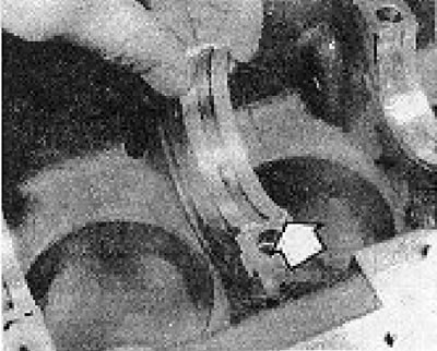
Photo 4B.222. When installing the bearing shell, the protrusion on it should fit into the recess in the cylinder block (shown by the arrow).
223. The axial movement of the crankshaft is checked at bearing No. 4.
224. Thrust washers are installed on both sides of bearing No. 4 (see photos).
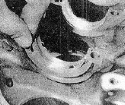
Photo 4B.224A. Installing thrust washers on bearing No. 4.
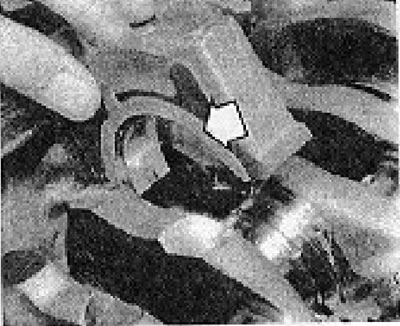
Photo 4B.224B. Installing bearing cap No. 4 (the thrust washer is shown by the arrow).
225. The radial clearance of bearings can be measured (if necessary, also on the engine standing on the car) using Plasigage thread.
226. Remove the bearing cover.
227. Clean the bearing shell and crankshaft journal.
228. Fold a strip of Plasigage across the neck.
229. Install the bearing shell and cover and tighten the cover bolts to a torque of 65 Nm.
230. Remove the bearing cover.
231. Measure the width of the Plasigage strip and compare it with the scale included with the kit.
232. If the main journals are worn beyond the permissible limits, the crankshaft must be reground (see Chapter 1, Section 19).
233. Beginning in February 1984, a longer needle bearing was installed at the rear end of the crankshaft (see photo).
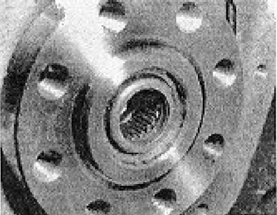
Photo 48.233. Crankshaft needle roller bearing.
234. Due to its greater length, the new needle roller bearing has a shallower installation depth.
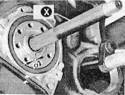
Figure 13.16. Installing a needle roller bearing into the flywheel (section 4B). a - Installation depth: Old type bearing = 5.5 mm; New type bearing = 1.5 mm; x - Suitable tool for driving the bearing.
235. Lubricate the bearing with molybdenum grease.
Assembly
236. The engine assembly is generally carried out in accordance with the procedure specified in chapter 1, Section 21, and the sequence reverse to the sequence of its disassembly (see this Appendix).
Installation
237. The engine is installed in the reverse order of its removal, in accordance with the instructions of Chapter 1, sections 22 and 23.
Visitor comments