
English Русский
Български
Беларускі
Український
Српски
Hrvatski
Română
Polski
Slovenský
Magyar
  |  Articles  |  Sitemap  |  Contacts  |    |
Car maintenance Ford Car maintenance Hyundai Car maintenance Chevrolet Car maintenance BMW Car maintenance Audi Car maintenance Opel Car maintenance AvtoVAZ
VWmanual.ru


Main   Passat   Golf   Polo   Touareg   Tiguan   Sharan   Transporter   Others  
Passat B2 (1981-1988) Passat B3 (1988-1993) Passat B4 (1988-1996) Passat B5 (1996-2005) Passat B6 (2005-2010)

Removal and installation a turbocharger on an AFN engine (VW Passat B4)

  • Main
  • Passat
  • Passat B4
  • Diesel engine
  • Turbocharging system
  • Removal and installation a turbocharger on an AFN engine
            0


To remove, turn the instrument and starter switch key to the "Off" position. Disconnect the wire from the negative terminal of the battery. Remove the protective pan of the engine compartment. Remove the booster air duct connecting the turbocharger to the air-to-air heat exchanger of the turbocharging system, and the intake air duct running from the air filter to the turbocharger. Disconnect the supply oil line from the turbocharger, remove the clamp securing the turbocharger to the intake manifold. Disconnect the inlet pipe of the extinguishers from the turbocharger. Remove the bracket securing the turbocharger to the cylinder block. Disconnect the drain oil line from the turbocharger.

Unscrew the nuts of the lower mounting studs from below and the nut of the upper mounting stud of the turbocharger to the exhaust manifold from above and remove the turbocharger through the top.

To install, apply Volkswagen G 000 500 heat-resistant grease to the threads of the turbocharger studs and the exhaust manifold. Install the turbocharger on the exhaust manifold and tighten the nut of the upper mounting stud. Tighten the nuts of the lower turbocharger mounting bolts and tighten them to a torque of 2.5 kgf·m. Connect the oil drain line with a new sealing gasket to the turbocharger and tighten its mounting bolts to a torque of 3.0 kgf·m. Install the turbocharger mounting bracket to the cylinder block and tighten its M8 bolts to a torque of 2.5 kgf·m, and the M10 bolts to a torque of 3.0 kgf·m. Tighten the nut of the upper turbocharger mounting stud to a torque of 2.5 kgf·m.


Attach the exhaust pipe to the turbocharger with a new gasket and tighten the nuts of the mounting studs to a torque of 2.5 kgf·m. Fill the turbocharger with oil through the oil supply pipe. Attach the oil supply line and tighten its mounting nipple to a torque of 2.5 kgf·m. Tighten the nuts of the mounting bolts of the oil supply line bracket to a torque of 1.0 kgf·m. Install a new gasket on the air intake duct and tighten the bolts of its mounting to the turbocharger and intake duct to a torque of 1.0 kgf·m.

Attach the vacuum hose to the wastegate valve and the air-to-air heat exchanger. Attach the air line that connects the turbocharger to the air cleaner.

Disconnect the boost air line connecting the turbocharger air-to-air heat exchanger to the intake manifold. Disconnect the vacuum hose from the EGR valve.

Attach the hand vacuum pump hose to the valve. While creating a vacuum with the hand vacuum pump, observe the valve diaphragm stem, which should move in the direction shown by the arrow (Fig. 3-61). Disconnect the hand vacuum pump hose from the valve. The valve stem should move in the direction opposite to that shown by the arrow.
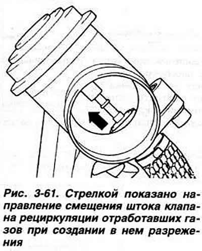
Attach the hand vacuum pump hose to the valve. While creating a vacuum with the hand vacuum pump,…


Note: After installing the turbocharger, start the engine and let it idle for approximately 1 minute to restore oil circulation through the turbocharger bearings, and only then can the engine be operated in operating modes.


The turbocharging system components are shown in Fig. 3-60.
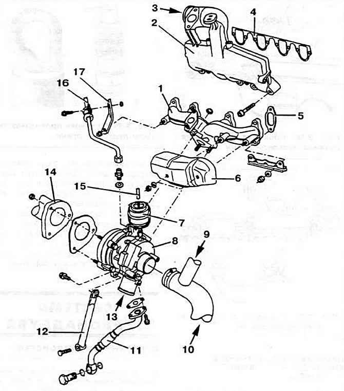
Fig. 3-60. AFN engine turbocharging system parts:

Fig. 3-60. AFN engine turbocharging system parts:
1 - inlet manifold;
2 - exhaust manifold;
3 - air supply from the air-to-air heat exchanger;
4 - intake manifold gasket;
5 - exhaust manifold gasket;
6 - heat shield;
7 — boost pressure limiting valve;
8 - turbocharger;
9 - from the crankcase ventilation system;
10 — air supply from the air filter;
11 — oil drain line;
12 — turbocharger mounting bracket;
13 - to the air-to-air heat exchanger;
14 — exhaust pipe;
15 - vacuum hose;
16 — oil supply line;
17 — bracket.


(View the original on the website: «www.VWManual.ru»)

This article is available at russian, bulgarian, belarusian, ukrainian, serbian, croatian, romanian, polish, slovak, hungarian
The text has been checked: Kolesnikov Artem

Share information:

Previous articles
Operating principle of a variable geometry turbocharger
Features of the turbocharging system
Checking the boost pressure
Removal and installation a turbocharger
Turbocharging system — general information
Next articles
Checking the exhaust gas recirculation solenoid valve
Checking the boost pressure


Similar articles from other manuals for VW cars:
Engine adjustment data Golf 1 (1974-1984, petrol)
Turbocharger for PD-TDI engine with a displacement of 1.4/1.9 l Polo 4 (2001-2009)
Car engine number Touareg 1 (2002-2006)
Car engine number Tiguan 1 (2007-2015)
Diesel engine fuel system and turbocharger Sharan 1 (1995-2000)
Starting the engine from another source Transporter T4 (1990-2003)
Visual inspection of parts in the engine compartment and on the… Caddy 3 (2003-2010)
Link to this page in different formats


Visitor comments


No comments yet


How much will 42 + 50 =


Passat B6 
  • General information
  • User manual
  • Maintenance
  • Petrol engine 1.6L
  • Engine repair
  • Cooling and lubrication system
  • Fuel injection system
  • Petrol engine 2.0L
  • Engine repair
  • Lubrication system
  • Cooling system
  • Fuel and exhaust systems
  • Diesel engine 2.0L
  • Engine repair
  • Cooling and lubrication system
  • Fuel and exhaust systems
  • Transmission
  • Clutch
  • Mechanical gearbox
  • Automatic gearbox
  • Drive shafts
  • Chassis
  • Wheels and tires
  • Car suspension
  • Steering
  • Brake system
  • Body
  • Exterior (external elements)
  • Electrical equipment
  • Power devices
  • Lighting and appliances
  • Electrical circuits
Passat B5 
  • General information
  • User manual
  • Weekly checks
  • Maintenance
  • Power unit
  • Engine repair
  • Cooling system
  • Fuel system (petrol)
  • Fuel system (diesel)
  • Engine management
  • Exhaust system
  • Transmission
  • Clutch
  • Car gearbox
  • Drive shafts
  • Chassis
  • Car suspension
  • Wheels and tires
  • Steering
  • Brake system
  • Body
  • Exterior (external elements)
  • Interior (internal elements)
  • Doors and covers
  • Ventilation and heating
  • Electrical equipment
  • Power devices
  • Lighting and appliances
  • Electrical circuits
Passat B4 
  • General information
  • User manual
  • Maintenance
  • Technical data
  • 8-valve engine
  • Engine repair
  • Cooling and lubrication system
  • Supply system
  • Ignition system
  • Fuel injection «Mono-Jetronic»
  • Control system «Mono-Motronic»
  • Control system «Digifant»
  • Control system «Simos»
  • 16-valve engine
  • Engine repair
  • Cooling and lubrication system
  • Fuel injection «K-Jetronic»
  • Control system «KE-Motronic»
  • Control system «Digifant»
  • Diesel engine
  • Engine repair
  • Cooling and lubrication system
  • Power and control system
  • Turbocharging system
  • Digital control system
  • Transmission
  • Clutch
  • Manual gearbox
  • Hydromechanical gearbox
  • Front wheel drive
  • Chassis
  • Car suspension
  • Steering
  • Brake system
  • Body
  • Body elements
  • Electrical equipment
  • Power devices
  • Lighting and appliances
  • Electrical circuits
Passat B3 
  • General information
  • User manual
  • Driving Tips
  • Maintenance instructions
  • Technical data
  • Power unit
  • Engine repair
  • Ignition system
  • Lubrication system
  • Cooling system
  • Supply system
  • Petrol injection system
  • Diesel engine
  • Exhaust system
  • Transmission
  • Clutch
  • Car gearbox
  • Chassis
  • Suspension
  • Steering
  • Brake system
  • Wheels and tires
  • Body
  • Exterior
  • Interior
  • Heating system
  • Electrical equipment
  • Power devices
  • Lighting system
  • Equipment and devices
  • Wiper system
  • Electrical circuits
Passat B2 
  • General information
  • Introduction to instructions
  • User manual
  • Power unit
  • Engines 4-cylinder FZ
  • Engines 4-cylinder
  • Engines 5-cylinder
  • Transmission
  • Clutch
  • Four-speed gearbox
  • Five-speed gearbox
  • Hydromechanical gearbox
  • Front wheel drive
  • Chassis
  • Front suspension
  • Rear suspension
  • Steering
  • Brake system
  • Body
  • Body elements
  • Electrical equipment
  • Equipment and devices
  • Electrical circuits
VWmanual.ru © 2016-2026 | Mobile version | News and articles | Sitemap: EN BG BY UA RS HR RO PL SK HU | Write message | Site search
Passat B2 • Passat B3 • Passat B4 • Passat B5 • Passat B6 • Golf 1, diesel • Golf 1, petrol • Golf 2, petrol • Golf 2 • Golf 3 • Golf 4 • Golf 5 • Polo 3 • Polo 4 • Touareg 1 • Tiguan 1 • Sharan 1 • Transporter T3 • Transporter T4 • LT 28 • LT 2D • Beetle • Caddy 3 •
Our website uses cookies to ensure functionality and convenience.