At low engine speeds, the kinetic energy of the exhaust gases is low. Under these conditions, the turbine of a conventional turbocharger rotates slowly and the boost pressure is low, while the turbine speed of the variable geometry turbocharger is much higher, which allows the boost pressure to be increased quickly. At low engine speeds, movable blades 2 (pic. 3-59) almost not deviated and the speed C of the exhaust gases flowing between them at the turbine inlet increases sharply, which entails an increase in peripheral speed U of the blades of the impeller 1 of the turbine and, accordingly, an increase in the compressor speed. The speed of the exhaust gases passing through the turbine is shown by the vector W. As the fuel supply is increased, both the amount of kinetic energy of the exhaust gases and the boost pressure gradually increase. The pneumatic actuator 6 is connected by a hose to the compressor housing and, as the boost pressure of the pneumatic actuator diaphragm increases, it moves the rod 5 and the rod 4, under the influence of which the angle of inclination of the movable blades 2 increases up to the maximum value. Thus, the exhaust gases, depending on the increase in the flow sections between the movable blades, reach the turbine at the same or lower speed as at low engine speeds, but at different angles. The turbine speed is reduced and stabilized at a value that is optimal for engine operation at high speeds. The regulation of the rotor speed by changing the passage section of the turbine nozzle apparatus ensures the rapid achievement of the required amount of boost and an increase in the engine torque at low speeds, which significantly improves its elasticity.
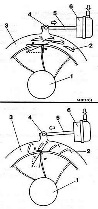
Pic. 3-59. Scheme of operation of a turbocharger on small (up) and high (at the bottom) engine speed:
1 - turbine impeller;
2 - movable blades;
3 - movable ring;
4 - stock;
5 - thrust;
6 - pneumatic actuator.

Visitor comments