
However, unlike the system «K-Jetronic», thanks to the presence of additional sensors, the system «KE-Jetronic» allows you to adapt the composition of the combustible mixture to the operating conditions of the engine. So. based on information from the coolant temperature sensors and the idle and full load contact switches, the electronic control unit (controller) issues commands to the electro-hydraulic control pressure regulator, which ensures the supply of the amount of fuel required for a given engine operation mode. In addition, the controller performs feedback between the fuel charge at the inlet to the combustion chamber and the products at the outlet, implemented by means of an oxygen content sensor in the exhaust gases. In the event of a malfunction of any element of the system, the controller switches to control the fuel supply according to the basic parameters, which allows you to continue driving the car. if the engine is warm. The enrichment of the combustible mixture required during a cold start and engine warm-up is determined by the signals of the coolant temperature sensor. The controller processes these signals and issues control signals to the electro-hydraulic control pressure regulator, which changes the fuel pressure in the lower chambers of the fuel dispenser pressure regulator. As a result, the combustible mixture is enriched.
During acceleration, the controller generates commands to increase the fuel supply based on the voltage signal from the potentiometer of the air flow meter, the value of which is proportional to the displacement of the pressure plate of the meter.
On forced idle (when releasing the accelerator pedal) the throttle valve returns to its original position. At the same time, the corresponding electrical signal is sent to the controller, which simultaneously receives information about the engine speed from the Hall sensor built into the ignition distributor. If indeed the rotational speed is within the speed range at which the fuel supply must be stopped at forced idle, the controller changes the direction of the control current passing through the winding 11 (pic. 2-200) electrohydraulic control pressure regulator. As a result, the damper 12 moves away from the nozzle 10, the pressure in the lower chambers 9 of the fuel distributor rises almost to the value of the control pressure and, under the action of the spring of the lower chambers of the diaphragm 8, closes the channels 3 and 5 for supplying fuel from the upper chambers of the distributor to the injectors. The moment of stopping the fuel supply at forced idle is determined by the temperature of the coolant. When the engine is warm, the fuel cut-off occurs as early as possible to avoid unnecessary fuel consumption. On a cold engine, the fuel cut-off time is extended so that a cold engine does not stop when the clutch is released abruptly.
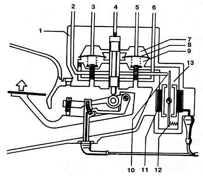
Pic. 2-200. The principle of operation of the fuel distributor and the electro-hydraulic control pressure regulator at forced idle:
1 - fuel distributor;
2 - fuel supply;
3, 5 - fuel supply to the nozzles;
4 - fuel supply;
6 - to the pressure regulator;
7 - upper chamber;
8 - diaphragm;
9 - lower chamber;
10 - nozzle;
11 - winding;
12 - damper;
13 - electro-hydraulic control pressure regulator.
The fuel supply is also stopped when the maximum permissible engine speed is reached. The idle speed of the engine crankshaft is automatically maintained by the rotary type regulator within the specified limits by the controller commands.
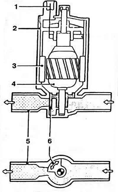
idle speed controller (pic. 2-201, 2-202) located in the bypass air channel, made parallel to the throttle valve, in place of the additional air supply valve. It is a permanent magnet actuator. A damper is installed on the armature shaft, which rotates, overcoming the force of the spring.
Pic. 2-201. Idle speed controller:
1 - block;
2 - body;
3 - permanent magnet;
4 - anchor;
5 - follower spring;
6 - rotary damper.
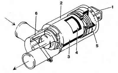
Pic. 2-202. Rotary Idle Control Diagram:
1 - output of the electrical connection;
2 - body;
3 - permanent magnet;
4 - anchor of the executive engine;
5 - air duct;
6 - rotary damper.
When the throttle valve is closed, the air passage is blocked to a certain extent by the regulator valve, which ensures the required engine speed at idle.
The idle speed controller is controlled by the commands of the control units of the controller. determining the degree of opening of the rotary damper, depending on the incoming information. At the same time, the controller changes the ignition timing accordingly. When the air conditioner is turned on at idle, the controller receives a signal from the air conditioner switch and, on command, the idle speed increases to 1000 rpm. This increases the efficiency of the air conditioner and ensures uninterrupted operation of the engine at idle.
When starting a cold engine and during warm-up, the idle speed controller acts as an additional air supply valve, ensuring that the idle mode is maintained within the specified limits regardless of the engine load.
Note. Some components of the system «KE-Jetronic» identical to similar components of the system «K-Jetronic». This applies, in particular, to the fuel filter, air filter, fuel pump, fuel priming pump, fuel pressure regulator, gas tank and other components.
The fuel dispenser-distributor installed on the air flow meter ensures uniform fuel supply to the injectors depending on the position of the pressure plate of the air flow meter. Brand and catalog number: Bosch 0 438 101 039.
A pressure accumulator installed in the fuel supply pipeline downstream of the fuel pump ensures that the residual fuel pressure in the system is maintained after the engine has been stopped and fuel supply fluctuations have been eliminated. Brand and catalog number: Bosch 0 438 170 061.
The control pressure regulator operates on signals generated by the controller based on information from the sensors. Brand and catalog number: Bosch 0 438 161 016.
The opening of the injector valves occurs under the influence of fuel pressure. Brand and catalog number: Bosch 0 437 502 043. Injection start pressure, kgf/cm2: 3,7-4,8.
The electromagnetic starting injector is used to enrich the mixture when starting a cold engine according to the signals from the controller. Brand and catalog number: Bosch 0 280 170 434.
The movable pressure plate of the air mass meter moves depending on the amount of air taken in. Its movement is transmitted to the distribution plunger of the fuel dispenser, thereby changing the amount of injected fuel. Brand and catalog number: Bosch 0 438 121 076.
Bosch brand idle speed controller based on a permanent magnet motor. It is installed in the bypass air duct, made parallel to the throttle valve, and is designed to dose air into the intake pipeline during start-up, warm-up and regulation of the engine idle. Based on the information from the sensors, the KSUD controller generates an electric current pulse in the primary winding of the ignition coil and controls the control pressure regulator. At the same time, the ignition timing and the amount of injected fuel are automatically stabilized depending on the engine operating mode. Brand and catalog number: Bosch 0 261 200 222.
Visitor comments