
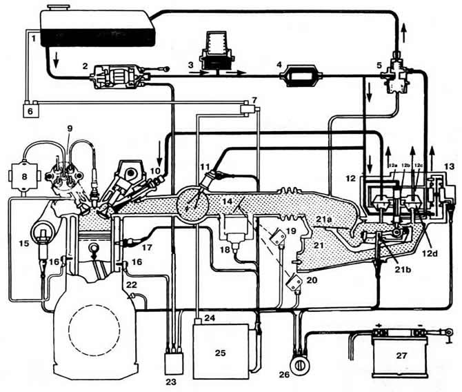
Pic. 2-199. Structural scheme of KSUD «KE-Motronic» engine «9A»:
1 - fuel tank;
2 - fuel pump;
3 - pressure accumulator;
4 - fuel filter;
5 —fuel pressure regulator;
6 - adsorber;
7 - solenoid valve purge adsorber;
8 - ignition unit (ignition coil with end stage power amplification);
9 - ignition distributor with built-in speed sensor (Hall Sensor);
10 - fuel injector;
11 - starting nozzle;
12 - dispenser-distributor of fuel;
12a - distribution plunger;
12b — working edge of the plunger;
12c - upper chamber;
12d - lower chamber;
13 - electro-hydraulic control pressure regulator;
14 - throttle valve;
15 - oxygen content sensor in exhaust gases;
16 - knock sensors;
17 - coolant temperature sensor;
18 - idle speed regulator;
19 - idle switch;
20 - full load switch;
21 - air flow meter;
21a - pressure disk;
21b - potentiometer;
22 - spark moment sensor in cylinder No. 4;
23 - relay for turning on the fuel pump;
24 - vacuum sensor;
25 - controller;
26 - ignition switch;
27 - battery.
Visitor comments