
English Русский
Български
Беларускі
Український
Српски
Hrvatski
Română
Polski
Slovenský
Magyar
  |  Articles  |  Sitemap  |  Contacts  |    |
Car maintenance Ford Car maintenance Hyundai Car maintenance Chevrolet Car maintenance BMW Car maintenance Audi Car maintenance Opel Car maintenance AvtoVAZ
VWmanual.ru


Main   Passat   Golf   Polo   Touareg   Tiguan   Sharan   Transporter   Others  
Passat B2 (1981-1988) Passat B3 (1988-1993) Passat B4 (1988-1996) Passat B5 (1996-2005) Passat B6 (2005-2010)

Disassembly and assembly of the cylinder head (VW Passat B2)

  • Main
  • Passat
  • Passat B2
  • Power unit
  • Engines 4-cylinder FZ
  • Disassembly and assembly of the cylinder head
            0


Contents: Disassembly ↓ Assembly ↓

Disassembly


Loosen the valve drive clearance adjusting bolts as much as possible so that the valve drive levers can be removed.

Remove the lever retaining springs and the levers themselves (see photo).
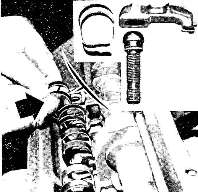
Removing the valve drive lever retaining spring


Remove the oil line.

Remove the camshaft from the cylinder head supports.

Compress the valve springs with a special device, release the valves from the crackers and remove the valves.

Remove the springs with plates.

Remove the valve stem oil seals and spring support washers using pliers 10 218.

If the removed parts do not need to be replaced, arrange them in order so that they can be installed in their original place during assembly.

Wash all removed parts.

Check the degree of wear of the valve guide bushings (for dimensions, see subsection "Design and technical characteristics").

Measure the clearance between the valve stem and the guide bushing using a stand with an indicator. To do this, insert a new valve into the guide bushing so that its stem is level with the edge of the bushing. Place the indicator leg on the valve head and measure the clearance.


Replace the guide bushings if the clearance exceeds the maximum allowable limit, which is 1.0 mm for intake valves and 1.3 mm for exhaust valves.

Using a ruler, check the non-flatness of the mating surface of the cylinder head and, if necessary, grind it.

Check the condition of the valve springs and valves.

Check the condition of the valve seats and grind them if necessary. Grinding should be carried out only with the help of special equipment and in compliance with the dimensions specified in the subsection "Design and technical characteristics".

If necessary, grind the working chamfers of the inlet valves. The working chamfers of the exhaust valves are not subject to grinding. Grinding of the exhaust valves is allowed, in other cases they are subject to replacement.

Before assembly, thoroughly clean the cylinder head.

Assembly


Install the valve spring support washers in place and insert the valves into the guide bushings.

Using the VW 10 204 mandrel, press new valve stem seals onto the guide bushings, then place the valve stem seal protective bushings onto the valve stems.

Install the valve springs and spring retainers. Install the crackers using a valve spring compressor.

Lubricate the bearing journals and cams of the camshaft with engine oil and install it together with the oil seal.

Install the levers onto the adjusting bolts.

Install the retaining levers by inserting them into the grooves of the adjusting bolts so that the springs rest on the levers.

Note: If the threads on the adjuster bolt bushing are damaged, a Heli-Coil or SEDC type threaded insert bushing can be used.


Using mandrel 10 203, press in the camshaft oil seal.

Install the camshaft toothed pulley and tighten its mounting bolt to a torque of 8 kgf.m.
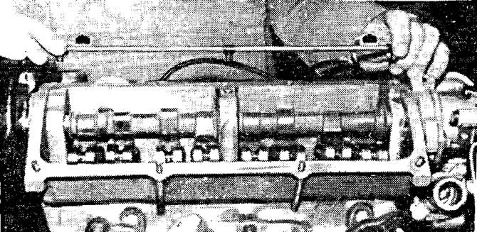
Removing the oil line
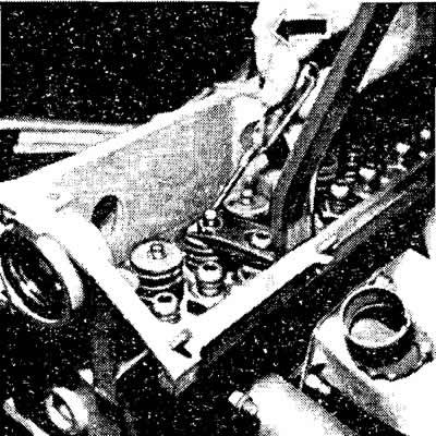


Removing valve crackers
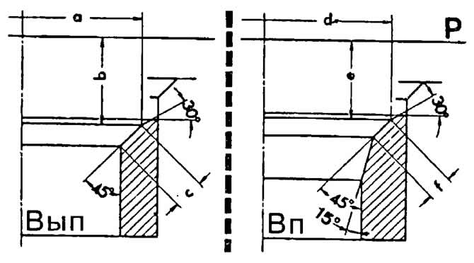


Dimensions for grinding valve seats:
Vp-intake valve seat;
Vyp - exhaust valve seat;
P — mating surface of the cylinder head;
a and d — outer diameter of the working chamfer of the valve seat;
b and e — recession of the working chamfer of the valve seat;
c and f — width of the working chamfer of the valve seat
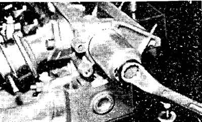

Pressing in the camshaft oil seal

This article is available at russian, bulgarian, belarusian, ukrainian, serbian, croatian, romanian, polish, slovak, hungarian
The text has been checked: Kolesnikov Artem

Share information:

Previous articles
Removal and installation the cylinder head
Adjusting the tension of the timing belt
Removal and installation the camshaft drive belt
Ignition system troubleshooting diagram, voltage testing
Setting the ignition timing
The principle of operation of the ignition system
Next articles
Removal and installation the engine
Disassembly and assembly of the engine
Preparatory stages of engine assembly
Engine assembly
Removal and installation of the oil pump of the lubrication system
Checking the oil pressure in the lubrication system


Similar articles from other manuals for VW cars:
Cylinder head Golf 1 (1974-1984, petrol)
Cylinder head Polo 3 (1995-2003)
Removal and installation the cylinder head cover Touareg 1 (2002-2006)
Cylinder head Tiguan 1 (2007-2015)
Removal the cylinder head Sharan 1 (1995-2000)
Removal and installation the cylinder head (petrol 4-cylinder) Transporter T4 (1990-2003)
Checking the cylinder head for warpage Caddy 3 (2003-2010)
Link to this page in different formats


Visitor comments


No comments yet


How much will 31 + 13 =


Passat B6 
  • General information
  • User manual
  • Maintenance
  • Petrol engine 1.6L
  • Engine repair
  • Cooling and lubrication system
  • Fuel injection system
  • Petrol engine 2.0L
  • Engine repair
  • Lubrication system
  • Cooling system
  • Fuel and exhaust systems
  • Diesel engine 2.0L
  • Engine repair
  • Cooling and lubrication system
  • Fuel and exhaust systems
  • Transmission
  • Clutch
  • Mechanical gearbox
  • Automatic gearbox
  • Drive shafts
  • Chassis
  • Wheels and tires
  • Car suspension
  • Steering
  • Brake system
  • Body
  • Exterior (external elements)
  • Electrical equipment
  • Power devices
  • Lighting and appliances
  • Electrical circuits
Passat B5 
  • General information
  • User manual
  • Weekly checks
  • Maintenance
  • Power unit
  • Engine repair
  • Cooling system
  • Fuel system (petrol)
  • Fuel system (diesel)
  • Engine management
  • Exhaust system
  • Transmission
  • Clutch
  • Car gearbox
  • Drive shafts
  • Chassis
  • Car suspension
  • Wheels and tires
  • Steering
  • Brake system
  • Body
  • Exterior (external elements)
  • Interior (internal elements)
  • Doors and covers
  • Ventilation and heating
  • Electrical equipment
  • Power devices
  • Lighting and appliances
  • Electrical circuits
Passat B4 
  • General information
  • User manual
  • Maintenance
  • Technical data
  • 8-valve engine
  • Engine repair
  • Cooling and lubrication system
  • Supply system
  • Ignition system
  • Fuel injection «Mono-Jetronic»
  • Control system «Mono-Motronic»
  • Control system «Digifant»
  • Control system «Simos»
  • 16-valve engine
  • Engine repair
  • Cooling and lubrication system
  • Fuel injection «K-Jetronic»
  • Control system «KE-Motronic»
  • Control system «Digifant»
  • Diesel engine
  • Engine repair
  • Cooling and lubrication system
  • Power and control system
  • Turbocharging system
  • Digital control system
  • Transmission
  • Clutch
  • Manual gearbox
  • Hydromechanical gearbox
  • Front wheel drive
  • Chassis
  • Car suspension
  • Steering
  • Brake system
  • Body
  • Body elements
  • Electrical equipment
  • Power devices
  • Lighting and appliances
  • Electrical circuits
Passat B3 
  • General information
  • User manual
  • Driving Tips
  • Maintenance instructions
  • Technical data
  • Power unit
  • Engine repair
  • Ignition system
  • Lubrication system
  • Cooling system
  • Supply system
  • Petrol injection system
  • Diesel engine
  • Exhaust system
  • Transmission
  • Clutch
  • Car gearbox
  • Chassis
  • Suspension
  • Steering
  • Brake system
  • Wheels and tires
  • Body
  • Exterior
  • Interior
  • Heating system
  • Electrical equipment
  • Power devices
  • Lighting system
  • Equipment and devices
  • Wiper system
  • Electrical circuits
Passat B2 
  • General information
  • Introduction to instructions
  • User manual
  • Power unit
  • Engines 4-cylinder FZ
  • Engines 4-cylinder
  • Engines 5-cylinder
  • Transmission
  • Clutch
  • Four-speed gearbox
  • Five-speed gearbox
  • Hydromechanical gearbox
  • Front wheel drive
  • Chassis
  • Front suspension
  • Rear suspension
  • Steering
  • Brake system
  • Body
  • Body elements
  • Electrical equipment
  • Equipment and devices
  • Electrical circuits
VWmanual.ru © 2016-2026 | Mobile version | News and articles | Sitemap: EN BG BY UA RS HR RO PL SK HU | Write message | Site search
Passat B2 • Passat B3 • Passat B4 • Passat B5 • Passat B6 • Golf 1, diesel • Golf 1, petrol • Golf 2, petrol • Golf 2 • Golf 3 • Golf 4 • Golf 5 • Polo 3 • Polo 4 • Touareg 1 • Tiguan 1 • Sharan 1 • Transporter T3 • Transporter T4 • LT 28 • LT 2D • Beetle • Caddy 3 •
Our website uses cookies to ensure functionality and convenience.