



The installation of the secondary shaft is carried out in the reverse order of dismantling (see figure 324). During the assembly process, the following recommendations should be followed:
- The thickness of the adjusting shim is determined based on measurements of the amount of play (see below).
- Tapered Bearing Race 3 (see figure 324) is pressed onto the shaft.
- The assembly of the synchronizer was described in the paragraph for the four-speed gearbox (model 084). The ends of the springs must be positioned as shown figure 296.
- The 11th gear pinion is installed on a needle bearing, then the synchronizer locking ring is inserted, and then the assembled synchronizer. The groove in the synchronizer cage should be directed towards 1st gear. The synchronizer is pressed until the recesses in its housing are in line with the locks.
- The 1st gear is installed with a synchronizer. Then the secondary shaft play should be adjusted if at least one part installed in the gearbox housing, the shaft or the tapered bearing, has been replaced. If there is no need to adjust the play, a tapered bearing should be installed on the shaft.
- Place the outer bearing race on or carefully install it into the gearbox housing on the clutch side together with a 0.65 mm thick adjusting washer.
- Install the secondary shaft assembly and the second part of the gearbox housing. Tighten the bolts to 25 Nm.
- Turn the secondary shaft several times and attach an indicator with a special plate and stand to its end (see figure 309 for analogy), but now install the plate on the end of the secondary shaft. Reset the indicator readings to zero, setting the initial preload value to 1.0 mm.
- Move the secondary shaft axially in both directions and read the indicator readings. Record the result (for example 0.30 mm.) It should be noted that the indicator must be reset after moving the shaft to one side, since the indicator arrow does not return to its initial position.
- Based on the obtained result, determine the thickness of the adjusting shim. To do this, add the thickness of the already installed washer, the indicator readings, and the bearing tension. For example, a 0.65 washer is installed. The measured value is +0.30 mm. The preload is +0.20 mm. In this case, the washer thickness is 1.15 mm.
- Remove the secondary shaft again, the outer bearing race and increase the washer thickness in the range from 0.65 to 1.40 mm.
- Install the outer bearing race with the selected adjusting washer into place in the gearbox housing on the clutch side and tighten the housing mounting bolts to a torque of 25 Nm.
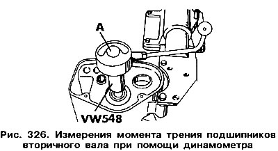
- Attach a special VW 54B attachment and a dynamometer to the secondary shaft to measure the friction torque (figure 326). Rotate the shaft using the dynamometer handle, which should show a torque of 0.80-0.160 Nm in the case of new bearings or no more than 0.30 Nm in the case of old bearings. Lubricate the bearings well before checking.
The installation of the primary shaft is carried out in the reverse order of dismantling (see figure 322). Adjusting the axial play of the shaft is necessary in case of replacement of one of the parts of the gearbox housing, the shaft itself or the tapered bearing. When installing the shaft, follow these instructions:
- Synchronizer 13 is assembled in the same way as in the four-speed gearbox model 084. The synchronizer cage and hub must be replaced as an assembly.
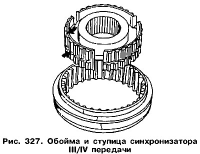
- The wider part of the synchronizer hub relative to the groove (indicated by the arrow in Figure 327) should be directed towards the gears of the fourth gear. Tapered bearing 19 (see figure 322) pressed onto the shaft with the cone facing outward.
- Lubricate the needle bearing 17 and install it on the shaft. Put the gear 16 of the third gear on the bearing. Install the locking ring 15 of the synchronizer, and then the retaining ring 12.
- Install the differential. The bearing preload should be adjusted as follows: described here.
- Clamp the primary shaft and install the synchronizer on it using a piece of pipe. Check the position of the groove on the edge of the splined surface of the hub (top arrow in figure 327) the correctness of its installation.
- Install retaining ring 12 (see figure 322) and insert the locking ring 14 of the synchronizer.
- Install gear 6 IV with needle bearing 5 and spring washer 4, and then put tapered bearing 3 on the shaft. If none of the above parts have been replaced with a new one, then the shaft can be installed in place without adjustment. Otherwise, it is necessary to adjust the axial play of the shaft.
- Insert the inner race of bearing 2 into the gearbox housing from the clutch side (see figure 32) without adjusting washer 1. Insert the primary shaft into the crankcase and bolt the two halves of the crankcase together (tightening torque 25 Nm).
- Attach a special stand with an indicator to the crankcase (see figure 309), but now install the plate on the end of the primary shaft. Turn the shaft several times.
- Set the initial indicator reading to 1.0.
- Move the primary shaft in the axial direction and read the indicator readings (for example 1.21 mm). Based on the obtained result, determine the thickness of the adjusting washer (similar to the secondary shaft - see above). There are washers of different thicknesses, which allows you to select a washer according to the obtained dimensions. It is recommended to take measurements several times.
- Remove the primary shaft and bearing race as shown in Figure 316.
- Install the bearing ring in place, inserting the selected (one or two) adjusting washers. Insert the input shaft and reconnect the two parts of the crankcase.
- Repeat the measurements. If the washer is selected correctly, the clearance should be 0.01-0.12 mm.
Next, the installation of parts is carried out in the reverse order of disassembly (see figure 313). However, it is worth paying attention to the following:
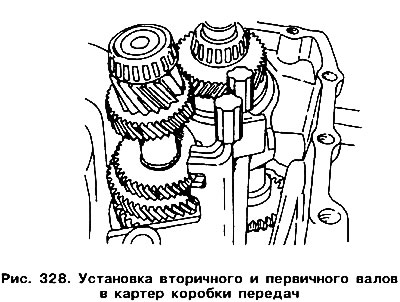
- Install the assemblies and parts shown in Figure 320 as a single assembly unit into the gearbox housing (figure 328).
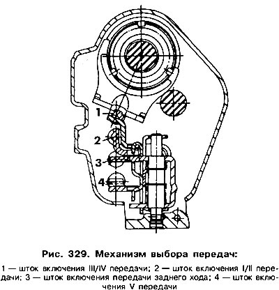
- Use a square to lift the reverse gear 8 and install the lever 6 and the reverse rod 5. After installation, the rods should take the position shown in Figure 329.
- Apply a layer of sealant to the mating surface of the crankcase and connect it with the gearbox crankcase on the clutch side. Press pins 11, 19 (see figure 313). Install the tie bolts and tighten to 25 Nm.
- Insert both drive shafts into the crankcase and screw in their mounting bolts. The tightening torque of the bolts is 25 Nm.
- Install the V gear on the primary shaft with the chamfer facing the tapered bearing and insert the retaining ring.
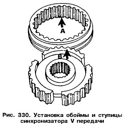
- Install the remaining parts of the V gear (see figure 312). The method of installing the synchronizer is shown in Figure 330. The synchronizer sleeve has three higher teeth (arrow A), and the synchronizer hub has a recess in the middle (arrow B), which must match. When installing the sleeve together with the forks, the 5th gear should be engaged, since otherwise the thread of the bolt with a round head can be damaged. Coat the bolt thread with a locking compound for threaded connections "D6". It should be noted that at the end of 1986 other bolts began to be used and the new bolt will not go along the old thread. Lock 6 (see figure 312) can be replaced with a retaining ring.
- When adjusting the V gear, it is necessary to rotate the spherical head bolt (arrow in figure 314) until the synchronizer sleeve is flush with its hub.
- Then engage 5th gear and tighten the spherical head bolt until the 5th gear forks select the gap in the groove of the synchronizer cage.
- Remove the bolt (approximately 1/8 of a turn), so that there is a small gap between the groove wall and the forks.
- Without turning the bolt, secure it with a lock nut.
- Secure the cover 2 (see figure 312) with a new gasket and bolts with a torque of 8 Nm.
Visitor comments