



Contents: Accelerator pump performance ↓ Throttle position ↓ Setting the "fast" idle mode ↓ Adjusting the idle speed parameters ↓ Idle Speed Increase Valve ↓ Setting the air damper position ↓
Accelerator pump performance
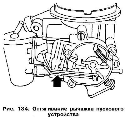
To evaluate the performance of the accelerator pump, the carburetor must be removed from the engine. Unscrew the liquid chamber of the starting device and pull the lever that controls the starting device with a rubber band (figure 134). This keeps the fast idle adjustment screw from coming into contact with the stepped disc.
Remove the carburetor cap, fill the float chamber with gasoline and reinstall the cap. Have a funnel and a glass measuring container ready.
Place the funnel into the measuring cup and place the carburetor over the funnel.
Open the damper 10 times with slow movements. Each opening movement should last at least 1 second, and after the movement there should be a three-second break.
The amount of fuel collected in the measuring cup should be divided by 10. The result should be (1.0±0.15) cm³.
If the pump is in good condition, i.e. its diaphragm, spring, sprayer and drive lever are functioning normally, then its performance can be adjusted, but within small limits.
- Screw in bolt 2 (figure 135), lock the cam that controls the accelerator pump.
- After removing the fuse, loosen the lock nut of the adjusting bolt 3.
- Slightly loosen screw 2 and turn the cam. By turning it in the "+" direction, we increase the pump's performance, and in the "-" direction, we decrease it.
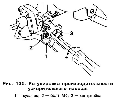
After making the adjustment, tighten nut 3 and lock it.
Throttle position
The throttle position is set at the factory, and the adjusting screw is sealed to maintain this position. But if, in an emergency, the factory adjustment had to be disturbed, it must be restored as follows.
Remove the liquid chamber of the starting device and pull the control lever with a rubber band (see figure 134).
Remove cap 1 from the adjusting screw (figure 136).
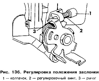
Turn the adjusting screw 2 until a gap is formed between its end and the lever that limits the movement of the damper 3. Then turn the screw until it touches the lever. To make it easier to record this moment, it is recommended to place a strip of paper between the screw and the lever. By moving the paper up and down and simultaneously turning the screw, you can accurately determine the moment of their contact.
From this position, turn the screw another 1/4 turn.
Close the screw with a new cap. Adjust the idle speed (see below).
Setting the "fast" idle mode
If the engine constantly stalls at idle without load, the so-called fast idle mode needs to be adjusted. The engine must be warmed up and have the ignition and idle parameters correctly adjusted. Connect the tachometer, remove the starter cover and set the fast idle adjustment screw 1 (figure 137) on the second from the top step of disk 2.
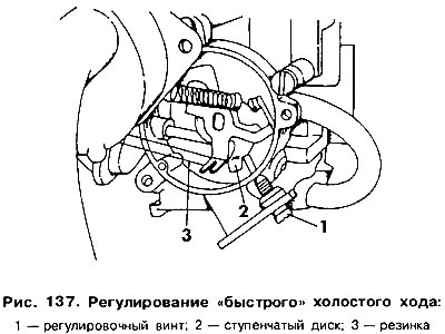
Pull back the rubber control lever of the trigger rod 3 to hold the damper in the fully open position.
Start the engine without pressing the accelerator pedal.
Check the rotation speed. It should be (2000±100) rpm. If necessary, adjust its value by turning screw 1.
Adjusting the idle speed parameters
Adjusting the idle speed parameters consists of setting the engine speed and adjusting the carbon monoxide content in the exhaust gases. These values are interdependent. Therefore, the idle speed is set first, and then the mixture composition is checked and possibly adjusted. The following conditions must be met before starting the adjustment operations.
The engine must be warmed up. Check whether the air damper is fully open, i.e. whether the damper lever touches the limiting bolt.
All electrical consumers must be switched off, this also applies to the radiator electric fan.
Disconnect the crankcase ventilation hose from the air filter and plug its end.
The ignition must be adjusted correctly.
Use a tachometer to check the idle speed. It should be (800±50) rpm. If necessary, adjust it using the adjusting screw (arrow in figure 127).
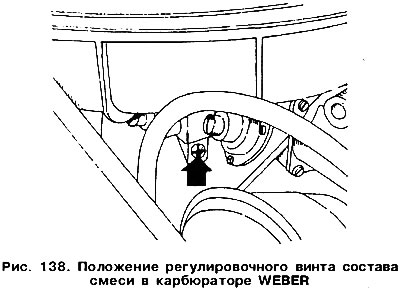
Using a gas analyzer, check the CO content in the exhaust gases. It should be within the range of (2.0±0.5)%. Otherwise, it should be adjusted using the adjusting screw (arrow 10 figure 138).
Connecting the ventilation hose from the cylinder block increases the CO content in the exhaust gases. This is due to the fact that oil vapors are always present in the engine crankcase.
After adjustment, place the blue cap on the screw.
Idle Speed Increase Valve
In order to avoid the idle speed falling below 700 rpm in certain engine operating modes, a vacuum-controlled valve located in the mixture quantity adjusting screw is activated. This opens an additional channel through which additional fuel is supplied to the carburetor, which causes an increase in the idle speed. The vacuum is supplied by a double valve, which is activated via a control device. Control of the increase in idle speed, as well as the operation of the valve built into the adjusting screw, requires a vacuum pump and must therefore be carried out at ASO VW service stations.
Setting the air damper position
The position of the starting (air) valve in the Weber carburetor can be adjusted. To do this, remove the starter cover.
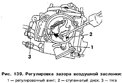
Set the fast idle adjustment screw 1 to the uppermost recess of disk 2, and move rod 3 with a screwdriver in the direction of the arrow (figure 139).
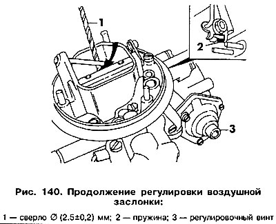
Insert a drill with a diameter of (2.5±0.2) mm between the edge of the air damper and the wall (figure 140). Make sure that spring 2 is not compressed. If the drill of the specified diameter cannot be inserted or it is inserted with a large gap, then the position of the damper should be adjusted using screw 3.
Visitor comments