
Accelerator pump performance
In order to check the performance of the accelerator pump without removing the carburetor, a vacuum pump is needed. If there is no such pump, the carburetor must be removed. Measure the pump performance using the method described below. Get your funnel and measuring cup ready.
Start the engine to fill the float chamber with gasoline. Remove the air filter and carburetor. Remove the carburetor carefully so as not to pour gasoline out of it.
Check disk 1 (pic. 145) so that it does not touch the fast idle adjusting bolt 2. Leave the dial in this position.

Place the carburetor over the funnel inserted into the beaker.
Turn the choke lever several times until fuel comes out of the atomizer. Make 5 full slow openings of the damper. Each movement must last at least 1 second with 3 second breaks. Divide the amount of gasoline collected in the beaker by 5, the result is the pump performance per membrane stroke (diaphragm). It must constitute (1,0±0,15) cm.
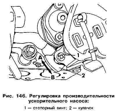
Adjust the pump output if necessary. Loosen lock screw 1 (pic. 146) and turn the cam 2. When turning in the direction of the arrow «A» pump performance increases, in the direction of the arrow «8» - decreases.
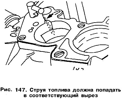
After finishing the adjustment, tighten screw 1 and fill the head with paint. The jet of fuel from the nozzle of the accelerator pump sprayer must exactly fall into the corresponding cutout (arrow in fig. 147). If this is not observed, the spray tube should be carefully bent with pliers. Adjustment is important and must be made in accordance with the drawing.
Installing the shutter of the 2nd chamber
Screw 2 (pic. 148), used to adjust the installation of the 2nd camera, is set at the factory. Its position cannot be changed. If necessary, adjust the position of the screw as follows:
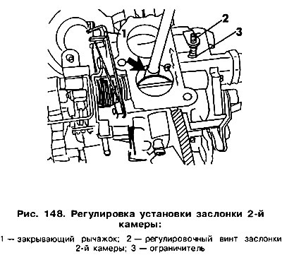
Open the shutter of the 1st chamber and block it by inserting a round rod (arrow in fig. 148).
Use a rubber band to pull lever 1, which serves to close the shutter of the 2nd chamber.
Unscrew screw 2 so that there is a small gap between its end and limiter 3 (thin paper thickness).
Screw in screw 2 again until it touches the limiter from this position, tighten it another 1/4 turn. In the s-th position, lock the screw with paint.
Remove the rubber band, remove the rod and check that both shutters are closed.
Check the gaps of the closing lever.
Gap «A» (pic. 149) should be equal to 0.25-0.55 mm, and «IN» - 0.85-1.15 mm.
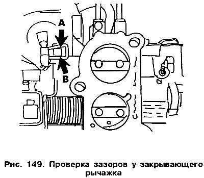
If necessary, correct the gaps by bending the lever frame.
After installing the carburetor, check the idle speed control with CO content measurement.
To check the choke gap, remove the starter cover.
Open throttle and rotate step dial 1 (pic. 150) so that the adjusting screw 2 rests on its highest step.
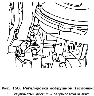
Pull the choke control rod all the way into the vacuum limiter.
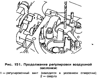
Insert a drill 2 between the air damper and the body (pic. 151) 2.7 mm in diameter. If the drill is not included (taking into account a tolerance of±0.10 mm), it is necessary to adjust with a screwdriver by turning screw 1.
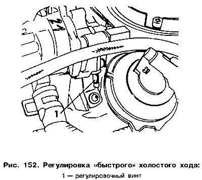
Installation «fast» idle move
If a cold engine stalls, then the so-called «quick» idle without removing the carburetor. The engine must be warm and the ignition and idle adjusted correctly, then do the following:
- Connect a tachometer.
- Remove the air filter and close the temperature controller connection.
- Start the engine.
- Check the engine speed and if it does not fall within the range of 1990-2100 rpm, it is necessary to set it with an adjusting screw (pic. 152). After that, lock the screw with paint to protect it from unscrewing.
- Check the idle speed setting and adjust if necessary.
Idle adjustment
The idling speed and the CO content in the exhaust gases are interdependent values. Therefore, you must first set the idle speed, and then you can proceed to check the composition of the exhaust gases. The engine must be warm and the adjusting screw «fast» idle must not touch the stepped disc.
All electrical consumers must be turned off, this also applies to the electric fan.
Disconnect the crankcase ventilation hose from the air filter and plug its end.
The ignition must be properly adjusted.
If a catalyst is installed, insert the probe of the gas analyzer into the nozzle used to measure the CO content.
The connection must be tight, otherwise erroneous results will be obtained. If there is an optional built-in microcatalyst, then the gas analyzer probe is inserted into the exhaust pipe.
Measure the idle speed with a tachometer. It must constitute (800±50) rpm If necessary, adjust it with the adjusting screw 1 (pic. 153).
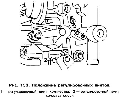
Check the CO content in the exhaust gases. It must be within (3,0±0,5) %. Otherwise, you need it. adjust with adjusting screw 2. To do this, remove the screw plug (blue color) and after the adjustment, install it in place.
Turn off the gas analyzer. With the catalytic converter installed, plug the CO measuring tube.
Install the crankcase ventilation hose.
Calibration data for carburetors are given in table 6.
Accelerator thrust adjustment
To adjust the working length of the rod, it is necessary to press the accelerator pedal and check the gap between the pedal and the floor at full throttle. This gap must be at least 5 mm. Otherwise release fastening of draft and rearrange draft in other flute. Check the clearance between the pedal and the floor again.
Possible malfunctions of the power supply system of carburetor engines are given below.
The prerequisites for troubleshooting using the data in the table is that the engine is correctly adjusted and running. ignition system and all auxiliary units, as well as a serviceable thermostat in the air filter. The exhaust system and air intake must be sealed. In addition, you should check whether the pressure of the fuel supply to the carburetor corresponds to the recommended one.
Visitor comments