
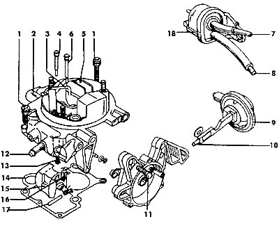
Pic. 116. SOLEX 1VZ carburetor cover: I - bolt (5 Nm), 2 - carburetor cover, 3 - enrichment system tube, 4 - additional air jet, 5 - air damper, 6 - idle air jet, 7 - fitting for the hose going to the vacuum brake booster, 8 - fitting to the adjusting screw amount of idling mixture, 9 - vacuum limiting device, 10 - adjusting screw for setting the air damper, 11 - bolt (5 Nm), 12 - fuel fitting, 13 - main fuel jet, 14 - gasket, 15 - float, 16 - needle valve, 17 - float shaft, 18 - two-way valve
When repairing a carburetor, use the following guidelines:
In no case should steel needles or metal wire be used to clean holes in jets and channels, as they can change the calibration of the flow sections of the jets.
Replace jets with jets with the same flow sections. Jets are carefully selected for this engine modification. The use of jets with large bores will not increase power, speed, etc., but may result in poor fuel economy.
For replacement, it is recommended to use only components manufactured by VW or manufacturers authorized by VW.
When working with parts made of aluminum alloys, do not use sharp tools. When tightening the connections, do not use much force, make sure that the bolt or screw is threaded. Threads in aluminum alloy parts can easily be damaged, which will compromise the connection and allow excess air to enter the mixing chambers.
To unscrew the jets, use only a screwdriver with a sharp tip of a suitable size and thickness in order to prevent damage to the slot of the jets. The needle valve is checked as follows: install the needle in the seat and blow into the fuel inlet fitting. Air must not pass. Repeat these steps with the needle removed - air should pass freely.
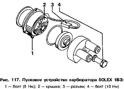
In case of complete disassembly of the carburetor, the operations must be carried out in the following sequence (pic. 116 and 117).
Remove the bolts securing the float chamber cover and remove the cover along with the gasket. The gasket must be replaced. Unscrew the needle valve from the cover. The fuel level is not subject to adjustment, it is fixed constructively.
Unscrew the head with fittings from the starting device and remove the rubber gasket.
Unscrew the starter cover and remove it together with the gasket.
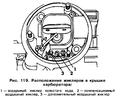
Unscrew the starter housing from the carburetor cover. Pay attention to the marks placed on the body and cover of the starter, as well as on the carburetor cover, as they must be aligned during assembly. Remove the idle air jet (pic. 119). Compensation air jets may contain emulsion tubes that cannot be replaced.
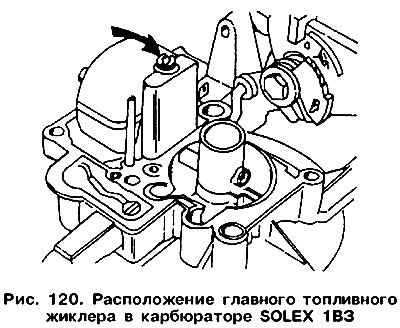
Turn out the main fuel jet (see fig. 120).
Remove the air damper actuator from the cover, and from the carburetor body with the solenoid valve for shutting off the fuel supply, the valve and the adjusting screw for the amount of mixture at idle.
The economizer valve is turned out only when it needs to be replaced. In other cases, its removal is unacceptable.
Remove the accelerator pump retaining ring and remove the pump parts from the hole.
Remove the float shaft from the carburetor body (from the middle out).
Remove the screw that regulates the quality of the mixture.
The carburetor is assembled in the reverse order. During assembly, follow the steps in the following subsections.
If the accelerator pump was removed, it is necessary to keep the sequence of mounting its parts, shown in fig. 118. The retaining ring is installed flush with the body surface.
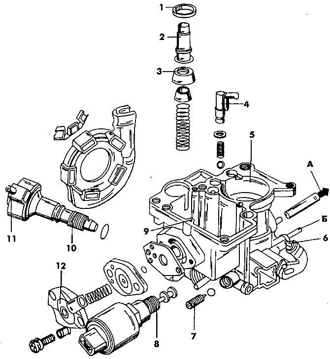
Pic. 118. The body of the float chamber of the carburetor: 1 - fixing ring, 2 - accelerator pump piston, 3 - piston seal, 4 - atomizer tube, 5 - housing, 6 - adjusting screw "fast» idle, 7. - adjusting screw, 8 - solenoid valve that cuts off the mixture flow, 9 - mixture enrichment jet at partial engine load, 10 - idle mixture amount adjusting screw with double valve, 11 - double valve, 12 - mixture enrichment valve when the engine is partially loaded, A - to control the vacuum limiting device, B - to the temperature controller in the air filter
The compensation air jet connected to the emulsion tube is not twisted. Its position is shown in Fig. 119. Nearby is air and additional idle jets.
The main fuel jet is located in the carburetor cap (pic. 120).
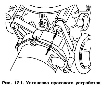
When installing the starting device, it is necessary to combine the marks on its cover: the risk and the dot on the carburetor cover (pic. 121). Tighten the cover bolts tightly and secure the head by placing new washers under the bolts.
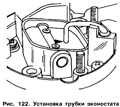
The econostat tube must be installed correctly. With the air damper closed, carefully bend the tube so that the distance between its end and the upper edge of the air damper is (1,0±0,3) mm. If the tube is lowered too deep, then the engine will not pick up speed at idle; if it is too high, it will be difficult to start it (pic. 122).
Pay attention to the correct assembly of the mixture enrichment valve (O-rings, springs, covers).
If the device that limits the vacuum has been replaced, you need to pay attention to the correct installation of it, as this may affect the operation of the carburetor when starting the engine.
The gap indicated by the arrow should be (1,0±0,3) mm.
Visitor comments