



The carburetor is equipped with two main metering systems: 1st and 2nd chambers, 1st chamber idle system with transition system, 2nd chamber transition system, 2nd chamber lock, power mode economizer, economizer, diaphragm accelerator pump, automatic mixed type starting device (bimetallic spring and electric heating). A pneumatic drive of the air damper and a device for electric heating of the intake manifold are used. The carburetor is equipped with a pneumatic drive of the throttle valve of the first chamber, controlling its movement in the idle and forced idle modes, as well as a pneumatic drive of the throttle valve of the second chamber. In the forced idle mode, the forced idle economizer is activated.
Disassembly and assembly of the 2EZ carburetor is similar to the disassembly of the previously described carburetors. The difference is in the removal of two vacuum chambers. The design of the carburetor is shown in Figures 141 and 142, and the position of the jets in Figures 143 and 144.
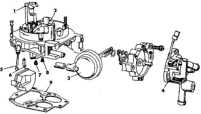
Figure 141. Carburetor cover PIERBURG 2E3: 1 - idle air jet and emulsion tube, 2 - power mode economizer tube, 3 - vacuum limiting device, 4 - starting device cover, 5 - fuel filter, 6 - needle valve, 7 - first chamber main fuel jet, 8 - second chamber main fuel jet, 9 - gasket
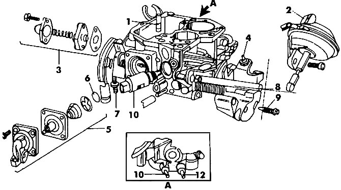
Figure 142. PIERBURG 2EZ carburetor body: 1 - distributor; 2 - vacuum chamber of the throttle actuator of the second chamber; 3 - mixture enrichment valve for partial engine load; 4 - "fast" idle speed adjustment screw; 5 - accelerator pump; 6 - gasket; 7 - limiter bolt; 8 - quantity adjustment screw with drive tube; 9 - mixture quality adjustment bolt; 10 - electromagnetic valve to stop the mixture supply; 11 - to the temperature regulator in the air filter; 12 - to the vacuum ignition advance regulator
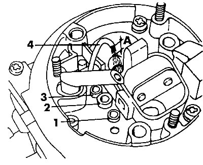
Figure 143. Jets in the carburetor cover 2EZ: 1 - idle air jet; 2 - compensating air jet with emulsion tube FOR the first chamber (can't be removed); 3 - compensating air jet with emulsion tube FOR the second chamber (can't be removed); 4 - sprayer; A=1 mm
(The original can be viewed on the portal: www.VWManual.ru)
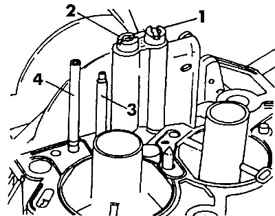
Figure 144. Location of jets in the lower part of the 2EZ carburetor cover: 1 - fuel jet of the main metering system of the first chamber; 2 - fuel jet of the main metering system of the second chamber; 3 - economizer tube; 4 - tube of the transition system of the second chamber
Visitor comments