
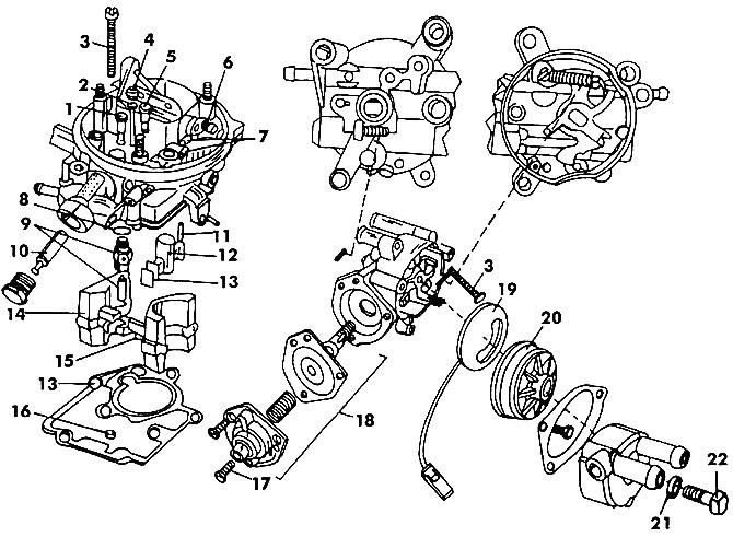
Pic. 129. Cover and semi-automatic starter carburetor WEBER TLA: I - additional fuel jet; 2 - emulsion tube; 3 - bolt (5 Nm); 4 - compensation air jet; 5 - idle fuel jet; 6 - air damper shaft; 7 - plug; 8 - gasket; 9 - needle valve; 10 - fuel filter; 11 - pin, 12 - atomizer; 13 - gasket; 14 - float; 15 - axis. float; 16 - main fuel jet; 17 - screw that regulates the installation of the launcher; 18 - vacuum limiting device; 19 - screen of a bimetallic spring; 20 - housing with bimetallic spring assembly; 21 - liquid chamber; 22 - gasket; 23 - bolt (10 Nm)
Pic. 130. WEBER TLA carburetor body: 1 - accelerator pump; 2 - atomizer; 3 - mixture enrichment valve at partial (incomplete) engine load; 4 - semi-automatic starting device; 5 - fitting to the screw for adjusting the amount of the mixture; 6 - fitting to the brake vacuum device; 7 - gasket; 8 - clamp; 9 - adjusting screw for the amount of the mixture; 10 - base with damper; 11 - gasket, always to be replaced; 12 - solenoid valve for stopping the supply of the mixture; 13 - fitting to the temperature controller; 14 - fitting to the vacuum ignition timing controller; 15 - adjusting screw «quick» idle move; 16 - screw that regulates the quality of the mixture
Attention! The mixture heating device is checked after disconnecting the connector. Connected between this connector and terminal «+» battery «probe» voltage (12V) should show the presence of tension.
Disassembly of the carburetor contains the following operations:
Turn out screws of fastening of a cover of the carburetor and remove it together with a lining. Replace gasket.
Remove the plug from the cap and remove the fuel filter.
Unscrew the needle valve.
Unscrew the fluid chamber from the starter body and remove the rubber gasket. The chamber is fixed with one bolt provided with a rubber gasket.
Unscrew the ring holding the starter cover and remove it. Under the lid is a mixture heater.
Remove the starter housing from the carburetor cover. Pay attention to the marks on the body and cover of the starting device, as well as on the carburetor cover. During assembly, they must be in line.
Turn out the jets shown in fig. 131. It should be remembered that the idle air jet 3 and the additional jet 6 do not turn out.
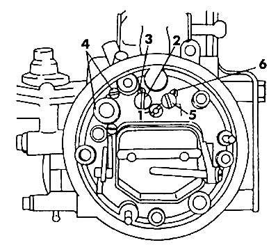
Pic. 131. The position of the jets in the carburetor cover: 1 - compensation jet; 2 - idle fuel jet; 3 - idle air jet (does not turn away); 4 - plug; 5 - additional fuel jet; 6 - additional air jet (does not turn away)
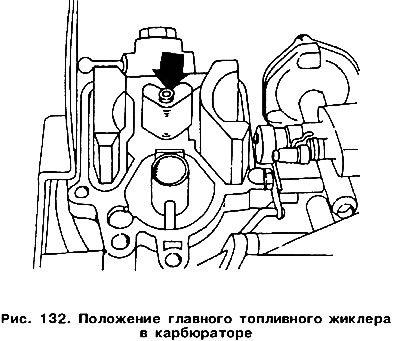
Turn out the main fuel jet (fig.132).
Remove the air damper control device from the cover, and the fuel shutoff solenoid valve and the idle mixture adjusting screw from the carburetor body. This screw is equipped with a valve that serves to increase the idle speed. The enrichment valve may only be turned out for the purpose of replacement.
Remove the accelerator pump cover and take out its parts. Pay attention to how the thrust is attached. The pump lever pin must fit into the top hole.
Remove the float with the axle from the carburetor cover. The axis is knocked out from the middle out.
Remove the screw that regulates the composition of the mixture (quality).
The carburetor is assembled in the reverse order. During assembly, perform the operations described in the following sections. Pay attention to the following.
The float chamber allows you to adjust the fuel level. Tilt the carburettor cap at a 45°angle to check that the float is properly installed (pic. 133) and measure the size «D», which should be 28 mm.
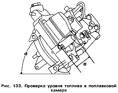
After installing the cover at an angle of 45°, the size «A» should be (28,0±1,0) mm.
If a different value is obtained, carefully bend the float to the appropriate side.
If the accelerator pump was removed, then the sequence of its installation is shown in fig. 130.
Screw the jets to the places shown in fig. 131 and 132.
During installation of the body with a bimetallic spring of the starting device, the end of the bimetallic spring must fall into a special groove in the body of the starting device. After installing the launcher, the labels on its body (arrow) and on the carburetor cap (dot) should be opposite each other. With the housing ring bolts firmly tightened, secure the fluid chamber by placing a new gasket under the bolt.
The atomizer tube must not move and, if it has been removed, must return to its original position when installed.
Pay attention to the correct assembly of the mixture enrichment valve (gaskets, center flange, diaphragms, springs, caps). Connect the leaner mixture when starting the engine.
Visitor comments