
English Русский
Български
Беларускі
Український
Српски
Hrvatski
Română
Polski
Slovenský
Magyar
  |  Articles  |  Sitemap  |  Contacts  |    |
Car maintenance Ford Car maintenance Hyundai Car maintenance Chevrolet Car maintenance BMW Car maintenance Audi Car maintenance Opel Car maintenance AvtoVAZ
VWmanual.ru


Main   Passat   Golf   Polo   Touareg   Tiguan   Sharan   Transporter   Others  
Touareg 1 (2002-2006)

Removal and installation the door lock (VW Touareg 1)

  • Main
  • Touareg
  • Touareg 1
  • Body
  • Outdoor elements
  • Removal and installation the door lock
            0


Contents: Removal ↓ Installation ↓
The frame of the wall-mounted units consists of a mounting frame and a glass frame.

The window lift, door lock and speaker are mounted on the frame of the mounted units.

The door lock can only be removed together with the frame of the mounted units.

Removal


Remove the front door trim.

Removing the lock cylinder housing.

Remove clip 1 from door handle 2 (fig. 8.30).

Pry off plugs 1 and 3 (Fig. 8.32).
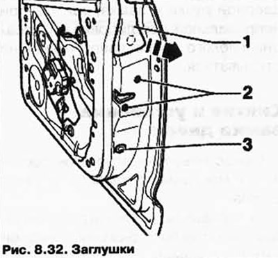
Pry off plugs 1 and 3 (Fig. 8.32).


Unscrew bolts 1 and 3 of the glass frame. Tightening torque: 20 Nm.

Remove screws 2 from the door lock. Tightening torque: 20 Nm.

Pry off plugs 1 and 5.

Unscrew bolts 2 and 4 of the glass frame (Fig. 8.33).
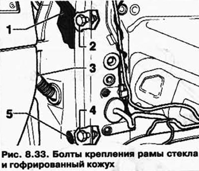
Unscrew bolts 2 and 4 of the glass frame (Fig. 8.33).


Remove the screws from the door lock. Tightening torque: 20 Nm.


Disconnect the corrugated casing 3 from the pillar A and disconnect the plugs.

Pass the housing and plugs through the hole into the door cavity.

Disconnect plug 2 from window lift motor 2 and pass it through the hole in the mounting frame (Fig. 8.34).
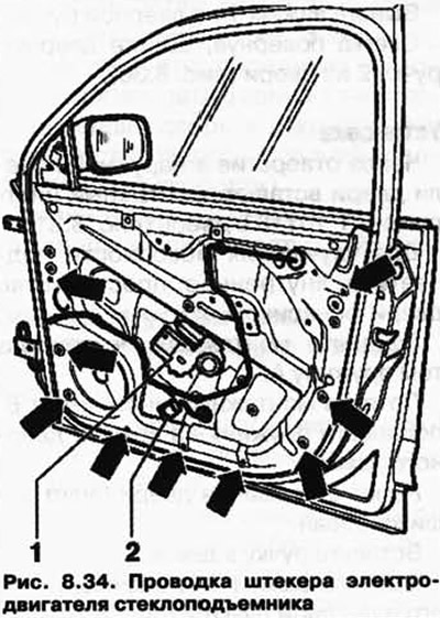
Disconnect plug 2 from window lift motor 2 and pass it through the hole in the mounting frame (Fig.…


Remove the bolts. Tightening torque: 8 Nm.

Gently pull the front of the attachment frame away from the outer door panel a.

Please ensure that the cables are not pulled tight.

Pull the frame of the hanging units towards the door hinges from the outer door panel b (Fig. 8.35).
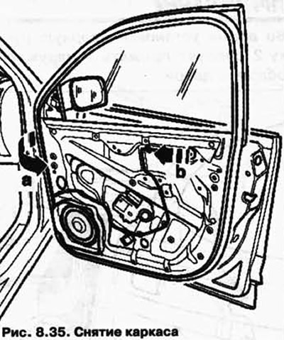
Pull the frame of the hanging units towards the door hinges from the outer door panel b (Fig. 8.35).


When doing this, make sure that the door lock does not catch on the outer door panel.

Drill out both rivets 1.

Disconnect plugs 3 and push rubber bushings 5 out of the frame of the mounted units (Fig. 8.36).
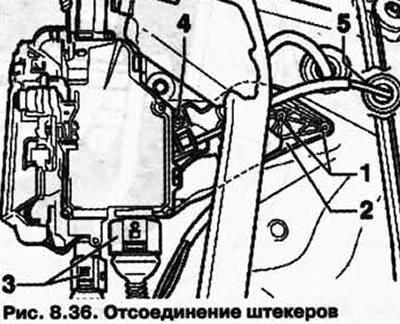

Disconnect plugs 3 and push rubber bushings 5 out of the frame of the mounted units (Fig. 8.36).


The corner holder is secured to the door lock using rivet 4 and a retainer.

NOTE: The retaining bracket is not included with the door lock. It must be replaced each time it is removed.


Disconnect flexible cable 1 from the door lock (Fig. 8.37).
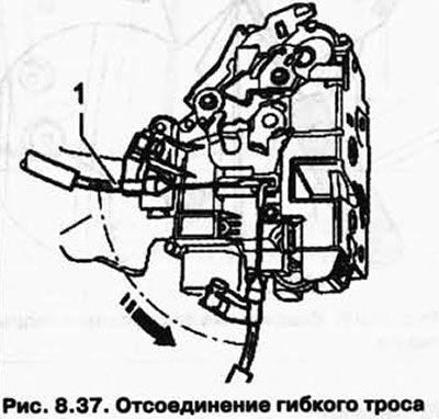
Disconnect flexible cable 1 from the door lock (Fig. 8.37).


Turn the flexible cable nipple 90° and remove it from the loop.

The door lock is installed in the reverse order.

Installation


Pull the drive lever 1 in the direction.

Using a screwdriver, tighten the spring 2 attached to the door lock in the direction of the arrow and hang the lock lever in the spring (Fig. 8.38).
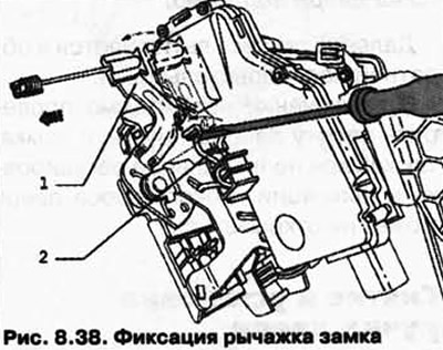
Using a screwdriver, tighten the spring 2 attached to the door lock in the direction of the arrow…


NOTE: By hanging the lever, you will lock the lock. This way, you can avoid possible "incorrect" fixation of the flexible cable.


Insert the frame of the hanging units into the door.

Insert the hinge side frame of the hanging units into the outer door panel a.

At the same time, make sure that the door lock fits freely into the niche in the outer door panel.

Press the frame of the suspended units at the front to the outer door panel b (Fig. 8.39).
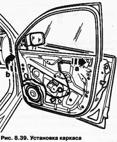
Press the frame of the suspended units at the front to the outer door panel b (Fig. 8.39).


Fit all bolts and tighten them. Tightening torque: 8 Nm.

Please ensure that the cable is routed correctly between the outer door panel and the glass frame.

NOTE: If the cable is pinched between the outer door panel and the glass frame, it may be damaged, causing malfunction of the electrical components built into the door.


Fit all bolts and tighten them. Tightening torque: 8 Nm.

Connect plug 2 to window lift motor 1 (Fig. 8.34).

Check that all three adjustment elements are fully tightened.

(The original article is posted on the website: VWMANUAL)

Tighten all four bolts - arrows - of the glass frame.

Position the glass frame in height and tilt exactly according to the contours of the car.

First tighten the top bolt on the hinge side.

After this, you should tighten the other three bolts in the adjustment elements.

Further installation is carried out in reverse order.

Finally, you should check the operation of the door lock.

This article is available at russian, bulgarian, belarusian, ukrainian, serbian, croatian, romanian, polish, slovak, hungarian
The text has been checked: Tarasov Ivan

Share information:

Previous articles
Removal and installation the door handle
Removal and installation the lock cylinder housing
Door adjustment
Removal and installation fuel tank hatch locking and unlocking elements
Removal and installation of the rear spoiler
Removal and installation the electric motor for opening the luggage compartment door
Next articles
Rear door adjustment
Removal and installation the rear door lock cylinder housing
Lift and slide sunroof with glass panel
Removal the glass panel of the lift-and-slide sunroof
Installing a glass panel for a lift and slide sunroof
Adjusting the glass panel of the lift-and-slide sunroof


Similar articles from other manuals for VW cars:
Removal and installation the rear door lock/cylinder housing Passat B3 (1988-1993)
Removal and installation the internal door lock button Golf 4 (1997-2004)
Removal and installation the rear door lock POLO Polo 4 (2001-2009)
Removal and installation the door lock bracket Tiguan 1 (2007-2015)
ABS (Anti-lock Braking System) Sharan 1 (1995-2000)
Door handle and lock — removal and installation Transporter T4 (1990-2003)
Primary lock of the rear door of a high van — removal and… LT 28 (1975-1991)
Link to this page in different formats


Visitor comments


No comments yet


How much will 26 + 33 =


Touareg 1 
  • General information
  • Vehicle device
  • Controls and instruments
  • Seats and safety
  • Maintenance and management
  • Power unit
  • Engine checks
  • Petrol engine 3.2L
  • Petrol engine 4.2L
  • Diesel engine 5.0L
  • Cooling system
  • Lubrication system
  • Injection system
  • Exhaust system
  • Fuel supply system
  • Transmission
  • Automatic gearbox 09D
  • Mechanical gearbox 08D
  • Cardan shaft
  • Chassis
  • Wheels and tires
  • Front suspension
  • Rear suspension
  • Steering gear
  • Brake system
  • Body
  • Outdoor elements
  • Electrical equipment
  • Battery
  • Generator and starter
  • Instruments and wipers
VWmanual.ru © 2016-2026 | Mobile version | News and articles | Sitemap: EN BG BY UA RS HR RO PL SK HU | Write message | Site search
Passat B2 • Passat B3 • Passat B4 • Passat B5 • Passat B6 • Golf 1, diesel • Golf 1, petrol • Golf 2, petrol • Golf 2 • Golf 3 • Golf 4 • Golf 5 • Polo 3 • Polo 4 • Touareg 1 • Tiguan 1 • Sharan 1 • Transporter T3 • Transporter T4 • LT 28 • LT 2D • Beetle • Caddy 3 •
Our website uses cookies to ensure functionality and convenience.