
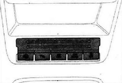
Removing and installing the button in the center console compartment
Instructions: The switches in the center console are located in the switch box. Removal and installation for all buttons in the center console compartment is carried out in the same way, so the description is given for only one switch. Depending on equipment, the following buttons are installed in the center console compartment.
- Clearance parking assistant button -E581-
- Parking aid button -E266-
- ASR and ESP deactivation button -E256-
- Button for cross-country driving -E620-
- Tire pressure monitoring display button -E492-
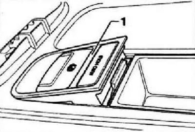
Switch off the ignition and all electrical consumers. Remove center console. Unlock and unplug all connectors at switch module -1-. Unlock both side locks -arrows- and pull switch block -1- upwards out of center console.
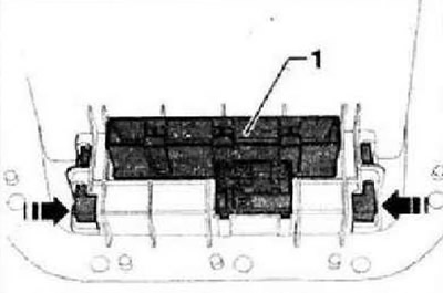
Installation is carried out in the reverse order.
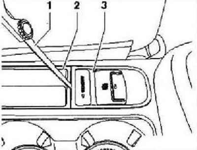
Electromechanical parking brake button and AUTO HOLD system button
The button for the electromechanical parking brake -ES38- and the button for the AUTO HOLD system -E540- are located in the switch module, which is integrated between the front seats in the center console.
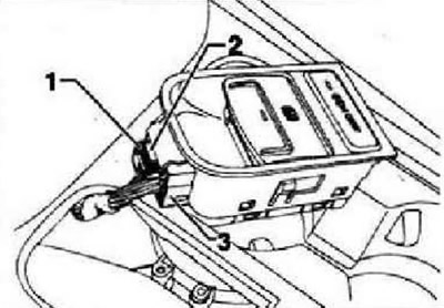
Switch off the ignition and all electrical consumers. Carefully (see fig.) insert probe (0.6 mm thick) -1- between center console 2 and key block -3-. Set the probe vertically and move it 10 mm down between the key block and the center console.
Instruction: The vertical position of the probe ensures that it enters the latch located on the back side. After deepening the probe by 10 mm, you should feel the touch of the protrusion of the latch.
Tilt feeler gauge -1- in -direction of arrow- to release catch -3-. Pull button block -2- out of center console -4- towards top and rear.
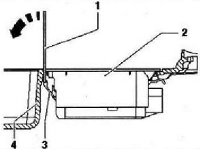
Remove switch module -1-, taking into account the lengths of the connected wires, upwards from the center console.
Remove primary lock -1-, press locking button -2- and remove plug -3-. Remove the switch module from the vehicle.
Installation is carried out in the reverse order.
Removing and installing inverter socket, 12 V-230 V -U13-
WARNING: The casing of the 12 V-230 V inverter socket -U13- contains capacitors that can be charged by residual voltage. Great danger of electric shock. Socket housing with inverter. 12 V-230 V -U13- must not be opened under any circumstances. The plug connections, cables and 230 V socket must not be repaired. If the plug connection, cables, 230 V socket or inverter are defective, the entire component must be replaced.
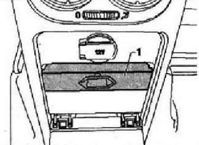
Switch off the ignition and all electrical consumers, remove the ignition key. Open cover of 230 V socket. Carefully press trim -1-.
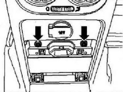
Remove screws -arrows-.
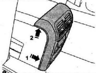
First, pull the lower cover slightly backwards in -direction of arrow 1- and then lift it up, taking into account the lengths of the connected wires, in -direction of arrow 2-.
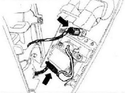
Unlock and unplug connectors -arrow- and remove trim.
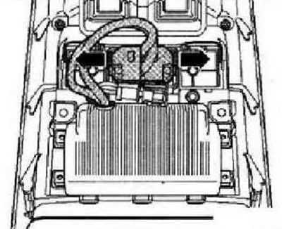
Unclip socket -arrows- and remove socket.
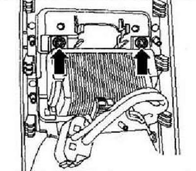
Unscrew both screws -arrows- and remove inverter with socket, 12V-230V from trim.
Installation is carried out in the reverse order.
Visitor comments