
Onboard supply control unit -J5J9-
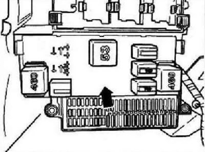
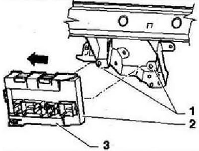
The onboard supply control unit -J519- -arrow- is located on the left under the dash panel on the left above the fuse box.
Note: The onboard supply control unit -J519- and the relay unit on the onboard supply control unit, dash panel on the left form a single unit and cannot be separated.
The onboard supply control unit -J519- performs the following tasks in the vehicle:
- Electrical load control
- Outdoor lighting control
- Turn signal management
- Wiper, rear window
- Rear window heating
- Interior lighting control
- Illumination backstage gearbox
- Terminal management
- Dashboard illumination with dimming
- Starting the fuel pump
- Generator pre-excitation
- Sound signal
The following functions of the onboard supply control unit -J519- can be set:
- Adaptation of the deactivation time for the heated rear window/exterior mirrors
- Delay time setting (Coming Home mode)
- High beam adaptation with adaptive lighting system
- Dimming adaptation for footwell lighting
- Delay time setting (Leaving Home mode)
- Reading the measured values of the onboard supply control unit
- Rain and light sensor coding
- Headlight cleaner adaptation
- Diagnosis of the final element of the onboard supply control unit
- Onboard supply control unit coding
- Wiper electronics control unit coding/APS deactivation
- Encoding/decoding daytime running lights
- Adapting the turn-on delay of the adaptive lighting system
Note: The ability to adapt the above functions depends on the vehicle equipment. Function "Turn signals on the autobahn", "Comfortable turning on of the direction indicators" or "Switching on the direction indicators with a short press" means that when you press the turn signal lever once, the turn signals will work several times (1-5) (turn signal cycles).
Fault recognition and error indication
The onboard supply control unit -J519- is equipped with a self-diagnosis system that facilitates troubleshooting. For troubleshooting, use the tester -VAS 5051 A- in the "Guided Fault Finding".
Removing and installing onboard supply control unit -J519-
Instruction: The onboard supply control unit -JS19- and the relay unit on the onboard supply control unit, dash panel on the left form a single unit and cannot be separated. If the onboard supply control unit -J519- needs to be replaced, first carry out the corresponding sequence of operations "Coding onboard supply control unit -J519-".
Convenience system central control unit -J393-
The convenience system central control unit -J393- is located under the dash panel on the right, under the glove box.
The convenience system central control unit -J393- can perform the following tasks:
- Hatch control (opening signal)
- Power window control (opening signal)
- Central door lock control
- Anti-theft alarm control
- Radio
- Closing the tailgate
- Comfort control
Note: When replacing the convenience system central control unit -J393-, the coding must be read "Replacing/coding convenience system central control unit -J393-".
Fault recognition and error indication
The convenience system central control unit -J393- is equipped with a self-diagnosis system that facilitates troubleshooting. For troubleshooting, use the tester -VAS 5051 A- in the "Guided Fault Finding".
Removing and installing convenience system central control unit -J393-
Note: When replacing the convenience system central control unit -J393-, the coding must be read "Replacing/coding convenience system central control unit -J393-".
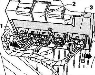
Switch off the ignition and all electrical consumers, remove the ignition key. Remove glove box. Push the locking lever -1- of the fastening -2- of the convenience system central control unit -3- in the direction of -arrow A-. While doing so, simultaneously move the central control unit -3- in the holder -2- by approx. 5 mm in the direction of -arrow B- into the first locking position.
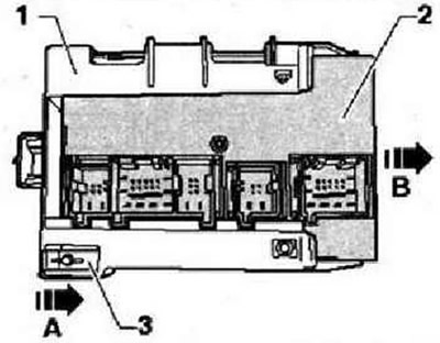
Note: For clarity, the convenience system central control unit is shown in the following figure in the removed state. The plugs can only be unlocked and disconnected if the grooves -arrows- of the plugs and the holder match exactly.
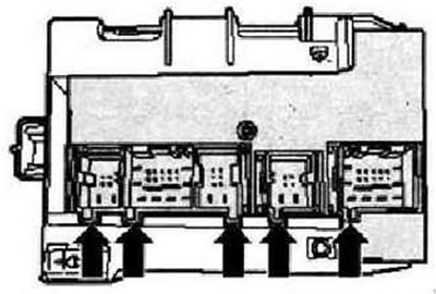
Unlock and disconnect plugs -arrows- from convenience system central control unit -J393-.
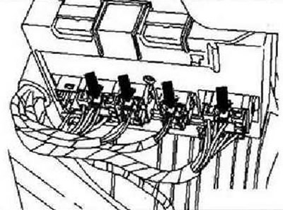
Instruction: The number of plugs depends on the vehicle equipment. All plugs can only be installed in one position, therefore no marking is required on the plugs. The convenience system central control unit -J393- -2- initially remains in holder -3-.
Unclip retainer -3- from retainers -1- and pull out -3- in direction of -arrow-.
Press locking lever -3- in -direction of arrow A- while sliding convenience system central control unit -J393- -2- out of holder -1- in -direction of arrow B-.
Installation is carried out in the reverse order. Insert the convenience system central control unit -J393- into the holder first only in the first locking position, so that the grooves -arrows- of the plug and the holder are exactly one above the other. Install connectors -arrows-. Push holder -3- together with connected control unit -2- onto retainers -1-. Insert the control unit -2- as far as it will go into the holder until the connectors are blocked (second fixation position).
Data bus diagnostic interface -J533-
The data bus diagnostic interface -J533- is mounted in the footwell on the driver's side, on the bracket for the heater. Data bus diagnostic interface -J533- (Gateway) made as a separate control unit. In the car, it performs the following tasks: carrying out information exchange between the CAN data bus "data bus CAN drive", "data bus CAN-Daterbus-comfort" And "data bus infotainment CAN", transfer of diagnostic data via the CAN data bus to the cable and vice versa, while this information can be used by the tester -VAS 5051 A-.
Note: When replacing the data bus diagnostic interface -J533-, the coding must be read "Replacing data bus diagnostic interface -3533-".
Fault recognition and error indication
The data bus diagnostic interface -J533- is equipped with a self-diagnosis system that facilitates troubleshooting. For troubleshooting, use the tester -VAS 5051 A- in the "Guided Fault Finding".
Removing and installing data bus diagnostic interface -J533-
The data bus diagnostic interface -J533- is mounted in the footwell on the driver's side, on the bracket for the heater.
Note: When replacing the data bus diagnostic interface -J533-, the coding must be read "Replacing data bus diagnostic interface -J533-".
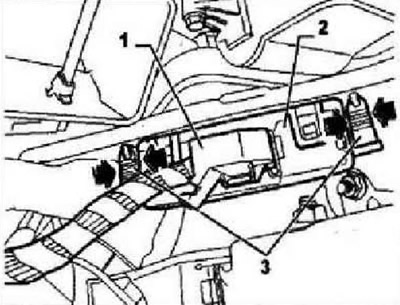
Switch off the ignition and all electrical consumers, remove the ignition key. Remove the trim on the driver's side on the left. Unlock and unplug electrical connector -1-. Press locking pins -3- in -direction of arrow- and remove data bus diagnostic interface -J533- -2- from bores. Remove data bus diagnostic interface -J533- from vehicle.
Installation is carried out in the reverse order.
Visitor comments