



Removal and installation of the switching block in the left part of a motor compartment
Instruction: At present, only the switching unit of the version "Low". The following figures show the option "High". Removing and installing the variant block "Low" carried out in a similar way.
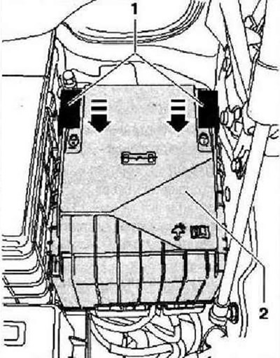
Disconnect battery. Slide locking clip -1- in -direction of arrow- and remove switch box cover -2- upwards.
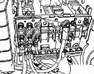
Unscrew hexagon nuts -1-. Open -arrows- the covers -2- of the cable guides on the connection box. Remove the cables from the connecting bolts. Unclip cables from their guides.
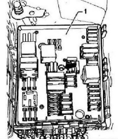
Unscrew the central fixing screw -arrow- of the electronics box -1-.
Note: By unscrewing the central fastening screw -arrow- the switching unit -1- will be pressed upwards from the holder of the switching unit.
Pull the switching unit -1- upwards out of its holder.
To remove the body with surface contacts, you must remove the air filter (only for vehicles with diesel engine), battery and its holder.
Diesel vehicles
Remove the air filter housing.
All
Remove the battery.
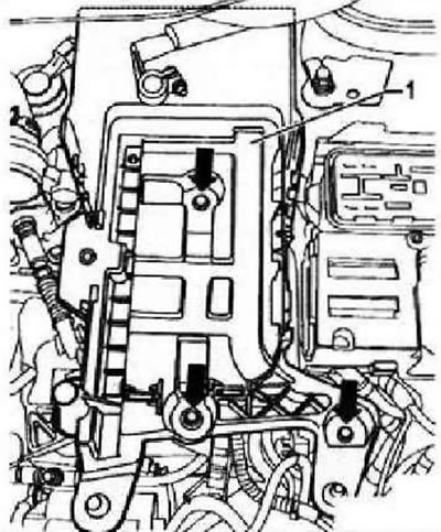
Remove securing screws -arrows- for battery holder -1-. Remove battery holder -1- from vehicle.
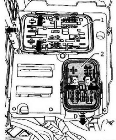
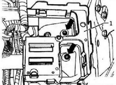
Unclip tabs on holder of electronics box -arrows B- and remove housing with surface contacts by moving housing -1 - to the side -arrow A-, from holder of electronics box. Unscrew securing nuts -arrows- of switch box holder -1-.
Note: The presence of an additional relay box depends on the vehicle equipment.
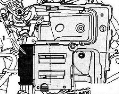
Pull out the holder of the switching box -1-, as far as the length of the cables of the additional relay box allows, upwards from the expansion bolt. Unclip additional relay carrier -1- from the side of the holder for the electronics box -2-. Remove holder for electronics box -2- from vehicle.
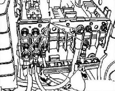
Installation is carried out in the reverse order. Connect the wires -1- in accordance with the accessories marked when removing them to the switching unit. Tighten screw connections to the specified tightening torques: fixing nuts -1- M5 (for 8): 4.5 Nm fixing nuts -1- M6 (on 10): 6 Nm.
Place cover -2- on switch box and slide locking clip -1- in -direction of arrow- until cover -2- snaps into place.
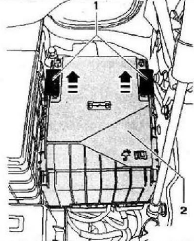
Instructions: Check that the cover -2- of the switching unit is fixed correctly.
Visitor comments