



Removal and installation of the fuse box
The fuse box is located under the dash, in the footwell on the driver's side. Switch off the ignition and all electrical consumers, remove the ignition key. Remove trim in driver's footwell. Remove securing screws -arrows- and pull fuse holder -1- downwards from holder.
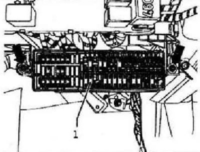
Installation in reverse order. Connect the fuse box first on the right side of the holder. Then turn the fuse box on the left side up to the stop and fasten it with two mounting bolts. Fastening bolt torque: 2.5 Nm.
Relay blocks
The relay boxes are located under the storage compartment in the footwell on the driver's side.
Removing and installing the relay box on the front panel
Disconnect battery. Remove the trim on the driver's side on the left.
Only vehicles with parking aid
Remove parking aid control unit -J791-.
All
Unlock catches -arrows A- and pull relay carrier -1- slightly downwards out of holder. Pivot relay carrier -1- under clip -arrow B-. Unlock connectors on reverse side of relay box -1-. Remove relay box -1- from vehicle.
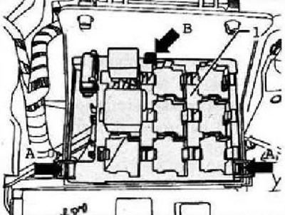
Installation is carried out in the reverse order.
Removing and installing the relay box on the onboard power supply control unit
The relay box on the onboard supply control unit, the dash panel on the left -arrow- is located under the dash panel on the left.
Note: The onboard supply control unit -J519- and the relay unit on the onboard supply control unit, dash panel on the left form a single unit and cannot be separated. When replacing the onboard supply control unit -J519- or relay unit, work must be carried out "Coding onboard supply control unit -J519-" for reading the encodings stored in the control unit.
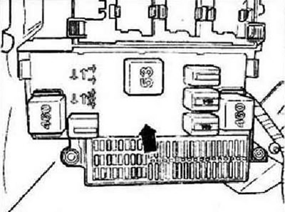
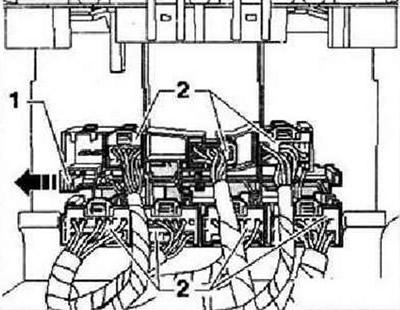
Switch off the ignition and all electrical consumers, remove the ignition key. Remove the gel protector panel. Move the locking latch -1- of the connectors of the relay carrier on the onboard power supply control unit -J519- in -direction of the arrow-.
Note: The connectors of the relay carrier on the onboard power supply control unit -J519- can only be removed if the safety latch has first been set to "AUF". The number of plugs and relays depends on the vehicle equipment. All plugs can only be installed in one position, therefore no marking is required on the plugs.
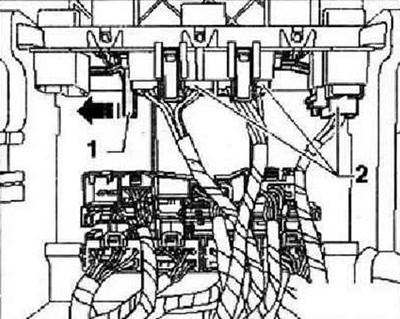
Unlock and disconnect plug -2-. Move the locking latch -1- of the onboard power supply control unit in -direction of the arrow- to position "OPEN". Unlock and disconnect plug -2-.
Unlock relay carrier at onboard power supply control unit -J519- -2- by unclipping retaining tabs -1- in direction of -arrow A- from retainer. Remove relay carrier at onboard supply control unit -J519- -2- in direction of -arrow B- from holder.
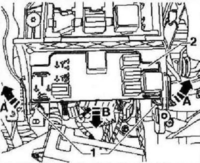
Installation is carried out in the reverse order.
Instruction: The safety lock can be set to the position "CLOSE" only if all plugs "Right" installed. After replacing the onboard supply control unit -J519-, it must be coded.
Visitor comments