



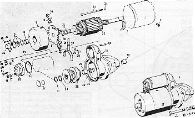
Figure 10.6. Detailed view of the Bosch starter motor (Section 9): 1 - Starter; 2 - Screw; 3 - Insulator; 4 - Screw with locking washer; 5 - Housing with solenoid winding; 6 - Brush holder; 7 - Commutator bearing; 8 - Bearing sleeve; 9 - Carbon brush; 10 - Spring; 11 - Drive bearing; 12 - Bearing sleeve; 13 - Solenoid; 14 - Washer; 15 - Solenoid cover; 16 - Clamp; 17 - Locking washer; 18 - Nut; 19 - Screw; 20 - Screw; 21 - Screw; 22 - Anchor; 23 - Gasket; 24 - Washers and C-washers; 25 - Gear; 26 - Bearing sleeve; 27 - Operating lever; 28 - Screw; 29 - Locking washer; 30 - Hexagonal Nut; 31 - Lock washer; 32 - Retaining ring; 33 - Screw; 34 - Regular washer; 35 - Dust cap; 36 - Screw; 37 - Washer; 38 - Screw; 39 - Regular washer; 40 - Washer; 41 - Hexagonal nut.
1. Maintenance should be limited to replacing brushes, replacing the solenoid, overhauling the drive gear and cleaning the commutator.
2. The main components of the starter should generally last as long as the starter itself, and if a failure occurs, a factory-made replacement should be purchased.
3. Disconnect the neutral winding wire from the solenoid contact.
4. Remove the screws that secure the solenoid to the drive end cover and remove the solenoid, at the same time disconnecting it from the drive arm.
5. Remove the dust cap from the end of the starter motor and take out the locking washer and various gaskets.
6. Loosen the connecting bolts and remove the rear motor cover.
7. Remove the carbon brushes from their holders and remove the brush mounting plate.
8. Remove the fastener from the drive end cover, and then unscrew the lever support bolt.
9. Remove the anchor together with the lever.
10 Using a piece of suitable tubing, push the retaining ring back off the armature shaft to gain access to the pusher ring. Remove the push ring and take out the starter drive components.
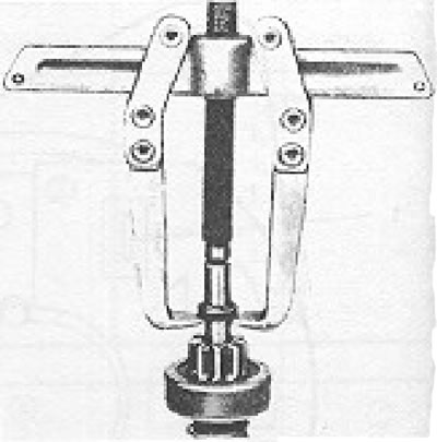
Figure 10.7. Pulling the starter drive retaining ring over the push ring (Section 9).
11. Measure the overall length of each of the two brushes and if they are worn to a length less than the Specifications, replace them by unsoldering the old ones and soldering new ones.
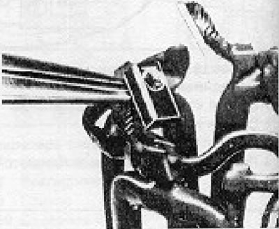
Figure 10.8. Starter motor brush wire ready for soldering (Section 9).
Make sure that each brush can move freely in the guides. If necessary, polish them with a fine file and remove any accumulated carbon from the holder with a cloth soaked in gasoline.
12. You can usually clean the commutator by rotating it by hand and pressing a cloth soaked in gasoline against it. If, upon inspection, the mica separators are found to be aligned with the copper segments, they should be trimmed by 0.5 to 0.8 mm. Trim the mica separators using an old jigsaw blade sharpened to the required level. The commutator can be polished with very fine sandpaper; never use emery cloth as the carborundum particles may become imprinted into the copper surface.
13. Wash the drive gear components in paraffin and inspect them for wear or damage, especially the gear teeth, and replace any if necessary.
14. Assembly is carried out by performing the above steps in reverse order. Lubricate the sliding surfaces with light oil, using a very small amount.
15. Note that the value of the anchor axial play must be within the limits specified in the Specifications. It can be adjusted by selecting washers located under the starter dust cap.
Visitor comments