



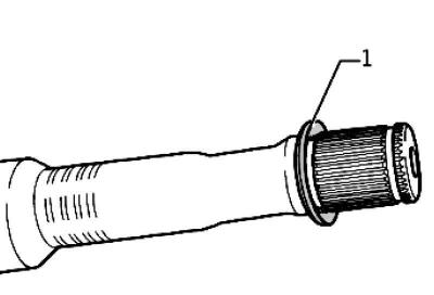
Fig. 3.109. Correct position of the inner CV joint disc spring: 1 – disc spring
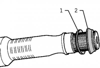
Fig. 3.110. Correct position of the disc spring and thrust washer of the outer CV joint: 1 – disc spring; 2 – thrust washer
If the hinge is assembled correctly, the collar in the housing can be freely rotated in any direction at an angle corresponding to the angle of rotation of the hinge.
Assembly
Press the hinge until it stops.
Install the retaining ring.
Pressing on the inner CV joint
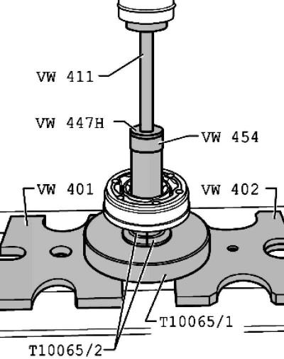
Fig. 3.111. Pressing on the inner CV joint
Note: The chamfer of the CV joint spline hole must face the spline end of the drive shaft.
Crimping the clamp on the outer hinge
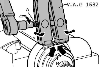
Fig. 3.112. Installing the collet chuck
Install the collet chuck as shown in Figure 3.112.
In this case, it is necessary to ensure that the crimping edges of the pliers are adjacent to the base of the protrusion B of the clamp.
Tighten the clamp by turning the lead screw with a torque wrench (without turning the pliers).
Note: Since the material of the dust cover (compared to rubber) it is quite rigid and requires a high-quality steel clamp to secure it. This clamp can only be crimped with pliers.
Tightening torque: 25 Nm.
Use a torque wrench C with an adjustment range of 5.50 N·m (for example, a torque wrench).
Make sure that the lead screw A of the pliers moves without jamming. If necessary, apply a small amount of MOS 2 grease.
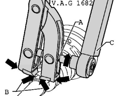
Fig. 3.113. Compression of a small clamp
If rotation is difficult, for example due to contamination of the thread, the required clamping force is not achieved at the specified tightening torque (fig. 3.113).
Visitor comments