



Contents: Removal ↓ Installation ↓
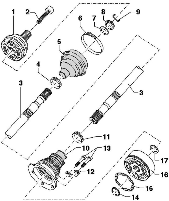
Fig. 3.97. Drive shaft components: 1 – Outer CV joint; 2 – Hexagon head bolt; 3 – drive shaft; 4 – clamp; 5 – CV joint boot; 6 – clamp; 7 – disc spring; 8 – thrust washer; 9 – retaining ring; 10 – CV joint boot; 11 – clamp; 12 – balancing washer; 13 – hexagon socket head bolt; 14 – retaining ring; 15 – seal; 16 – inner CV joint; 17 – disc spring
Removal
Loosen the hub bolt.
Remove the wheel.
Remove the coil spring.
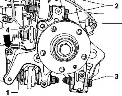
Fig. 3.98. Bolts for fastening the transverse rod and lower transverse arm
The original text is available on the website: vwmanual
Unscrew the bolts securing the transverse rod 1 and the lower transverse arm 3, connecting them to the hub bearing housing 4 (Fig. 3.98).
Unscrew the bolt.
Unscrew the mounting bolts and disconnect the drive shaft from the rear final drive flange.
Rotate the steering knuckle outward and remove the drive shaft from the hub splines.
Remove the drive shaft.
Installation
Installation is carried out in the reverse order, while it is necessary to observe the following instructions:
Tightening moments.
Tightening of the wheel bearing housing mounting bolts may only be performed after the dimension measured before installation between the wheel hub centre and the lower edge of the wheel arch has been reached.
Visitor comments