



Contents: Removal ↓ Installation ↓
Removal
The joint must be disassembled to replace the lubricant if it is heavily contaminated, and to inspect the surfaces that contact the balls for wear and pitting.
Turn the clip and separator.
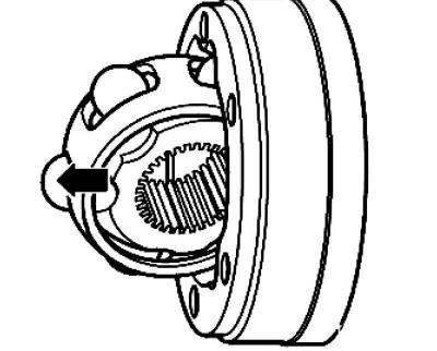
Fig. 3.104. Removing the clip and separator
Remove the cage with the separator and balls in the direction of the arrow (fig. 3.104).
(The original text can be found on the portal VWMANUAL.ru)
Remove the balls from the clip.
Note: The cage and separator are matched to each other (selective assembly). Do not install parts from other hinges.
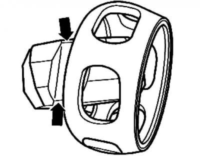
Fig. 3.105. Notches for balls
Remove the cage from the separator using the ball notches (fig. 3.105).
Check the housing, cage, clip, and balls for indentations (pitting) and signs of heavy wear.
The appearance of a knock when turning indicates an increase in the play in the joint. In such cases, the joint must be replaced. The matting of the surface of the balls and the presence of tracks from them are not a reason to replace the joint.
Installation
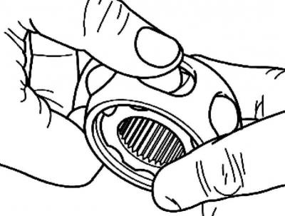
Fig. 3.106. Installing balls
Using the two ball recesses, insert the cage into the separator. The installation position is optional. Install the balls into the cage (fig. 3.106).
The cage has 2 different distances between the centers of the recesses for the balls - larger and smaller.
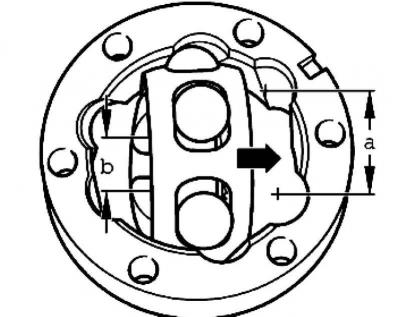
Fig. 3.107. Clip installation diagram
Place the cage and separator with balls into the joint housing, perpendicular to its plane, with the small distance B directed towards the outer part of the cage (fig. 3.107).
It is also necessary to monitor the position of the chamfer in the splined hole of the clip. The chamfer should be visible (is located outside) when the collar rotates parallel to the plane of the hinge housing.
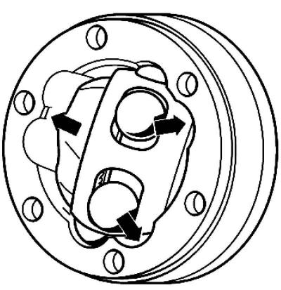
Fig. 3.108. Rotating the clip
Rotate the clip so that it comes out of the separator as far as possible (fig. 3.108).
Press firmly on the separator to rotate it into the proper position together with the cage and balls.
Visitor comments