



Features of the device
The Pierburg 2EZ carburetor is installed on "EZ" engines.
The plastic fuel tank with a capacity of 70 liters is installed under the body floor in front of the rear axle.
Fuel used: leaded or unleaded gasoline of the "Normal" brand with an octane rating of at least 95. The Bosch fuel filter is installed in front of the carburetor on the fuel supply hose.
Filter replacement frequency: every 20,000 km.
The fuel pump of the APG brand is mechanical, diaphragm type, driven by the eccentric of the intermediate shaft. The fuel supply pressure with the fuel drain hose disconnected is 0.35-0.40 kgf/cm².
Air filter Mann C31 152 with dry paper replaceable filter element and with a device for heating the incoming air.
Pierburg 2E3 carburetor, emulsion type, two-chamber, with sequential opening of throttle valves.
The carburetor has two main metering systems of the 1st and 2nd chambers, an idle system of the 1st chamber with a transition system, a transition system of the 2nd chamber, a lock of the 2nd chamber, an economizer of power modes, an economizer, a diaphragm accelerator pump, an automatic device for starting and heating of a mixed type, which uses a bimetallic spring with electric heating and circulation of heated liquid from the engine cooling system, and a pneumatic drive of the air damper and a device for electric heating of the intake manifold are used. The carburetor has a pneumatic drive of the throttle valve of the 1st chamber, which controls its movement in idle and forced idle modes, as well as a pneumatic drive of the throttle valve of the 2nd chamber. At forced idle, the economizer of the forced idle is activated.
Since the 1989 model year, starting with chassis number 31-K-000 001, the carburetor is equipped with a 2nd chamber throttle damper, which ensures that the throttle opens only when the engine is hot.
The main parts of the Pierburg 2E3 carburetor are shown in Fig. 2-33. The elements of the air tract of the carburetor engine are shown in Fig. 2-44.
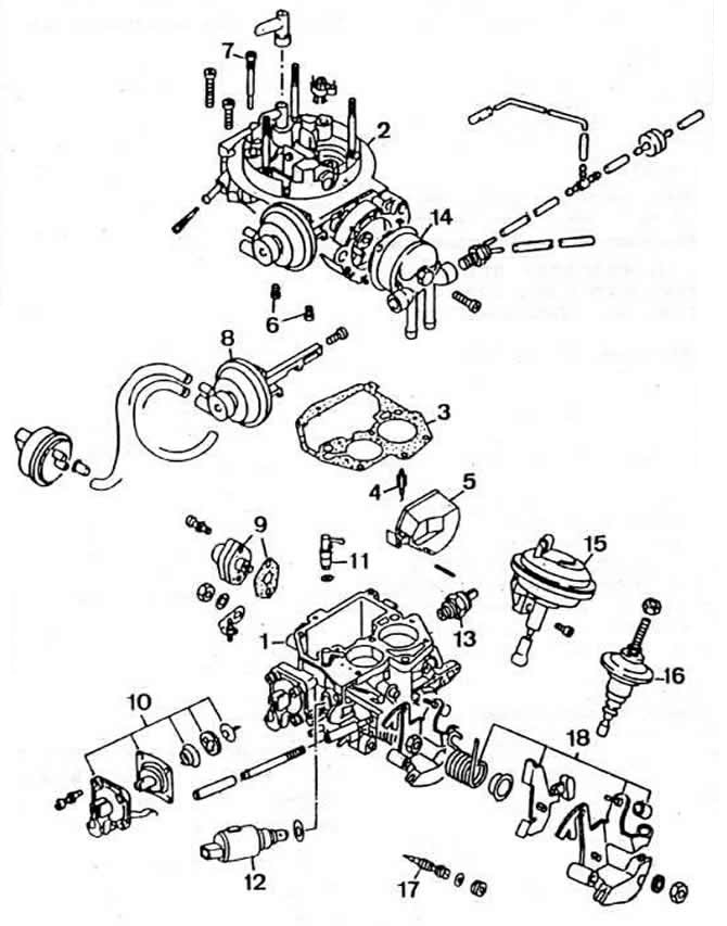
Fig. 2-33. Main parts of the Pierburg 2E3 carburetor:
1 - carburetor body;
2 - carburetor cover;
3 - cover gasket;
4 - needle valve;
5 - float;
6 - main fuel jets;
7 — idle fuel jet;
8 — pneumatic drive of the air damper;
9 — power mode economizer;
10 - accelerator pump;
11 - accelerator pump nozzle;
12 - electromagnetic shut-off valve;
13 — idle speed control heating unit;
14 - Automatic starting device;
15 — pneumatic drive of the throttle valve of the 2nd chamber;
16 — 2nd chamber throttle damper;
17 — adjusting screw for idle mixture quality (composition);
18 - throttle actuator parts.
Operating principle
Automatic starting device (Fig. 2-34). Carburetor operation diagram When starting a cold engine, pressing the accelerator pedal turns on the automatic starting device. Initially, the air damper is completely closed. After turning on the ignition, the heating circuit of the bimetallic spring located in the body of the automatic device closes, and the spring begins to heat up.
View the original on this portal www.VWmanual.ru
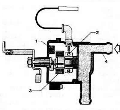
Fig. 2-34. Sectional view of the automatic starting device housing:
1—automatic starting device housing;
2 - heating element;
3 - bimetallic spring;
4 — coolant supply pipe.
When the engine is started, a significant vacuum is created under the air damper. The axis of the air damper is offset, so after starting the engine, the air damper opens under the vacuum by a certain amount depending on the counteracting force of the bimetallic spring. Immediately after starting the engine, in order to prevent over-enrichment of the combustible mixture due to a drop in pressure in the float chamber, the air damper opens by a certain amount by the pneumatic actuator rod. In this case, the engine enters the accelerated idle mode, and the adjusting screw is installed on the upper part of the profiled throttle control cam.
As the engine warms up, the crankshaft speed decreases as follows. When the accelerator pedal is pressed briefly, the fast idle speed adjusting screw, which is mechanically connected to the throttle valve, releases the profiled cam, which moves under the action of a bimetallic spring. After releasing the accelerator pedal, the fast idle speed adjusting screw is installed on the intermediate part of the profiled cam, as a result of which the throttle valve closes and the engine crankshaft speed decreases.
As the temperature of the bimetallic spring heating element and the coolant increases, the tension of the bimetallic spring weakens and the air damper gradually opens. When the coolant warms up to a temperature above 65°C, the power supply circuit of the mixture electric heating unit and the automatic starting device is opened by a thermal switch located in the intake manifold. In this case, the air damper is fully open, the fast idle adjusting screw no longer rests on the profiled throttle control cam, and the throttle valve of the 1st chamber occupies a position corresponding to the normal idle mode. Idle system (Fig. 2-36). When the engine is idling, the throttle valve of the 1st chamber is held in a slightly open position. Fuel from the float chamber enters the emulsion tube well through the main fuel jet of the 1st chamber and is fed to the idle fuel jet. At the outlet of the jet, the fuel is mixed with air passing through the idle air jet. The pre-prepared fuel-air mixture passes through the channel with the electromagnetic shut-off valve and is additionally mixed with air coming from the channel of the transition system. The finally prepared emulsion exits under the throttle valve through the hole adjusted by the mixture quality (composition) screw. The carburetor electric heating unit prevents its icing in adverse weather conditions.
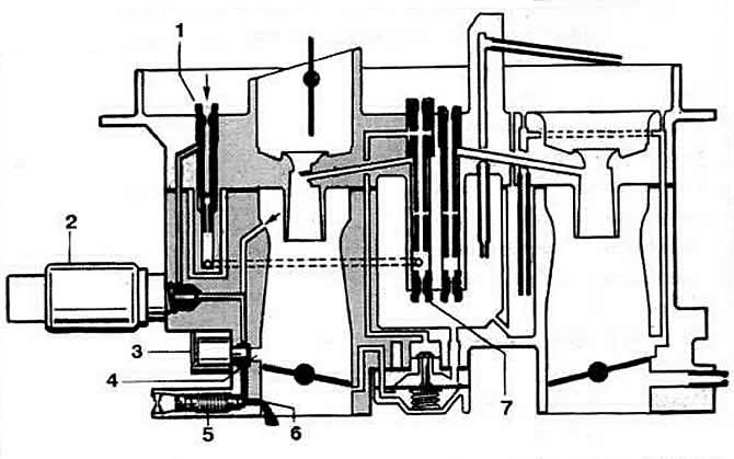
Fig. 2-36. Schematic diagram of the idle system and the transition system of the 1st chamber:
1 - idle air jet;
2 - electromagnetic shut-off valve;
3 — carburetor electric heating unit;
4 — transition system gap;
5 — adjusting screw for mixture quality (composition);
6 — idle system outlet;
7 - main fuel jet.
Transition system of the 1st chamber. When the accelerator pedal is pressed, the edge of the throttle valve forms a crescent-shaped gap in the area of the transition system slit, located above the outlet of the idle system. Under the action of vacuum, an additional amount of fuel-air emulsion enters the first chamber through the transition system slit, which ensures normal operation of the carburetor when switching from idle to load modes.
Accelerator pump (Fig. 2-37). As soon as the throttle valve of the 1st chamber moves away from the idle position, the spring moves the diaphragm of the accelerator pump back, which leads to filling the pump cavity with fuel. When the throttle valve opens, the profiled cam acts on the pump drive lever, which compresses the diaphragm of the pump. The inlet valve closes and the diaphragm, through the ball valve and the sprayer, pumps fuel into the main mixing chamber, enriching the combustible mixture.
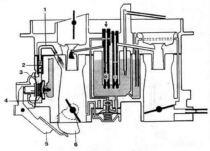
Fig. 2-37. Accelerator pump diagram:
1 - sprayer
2 - ball discharge valve
3 - diaphragm
4 - inlet valve
5 — pump drive lever
6 - profiled pump drive cam
The performance of the accelerator pump is regulated by changing the position of the profiled cam of the pump drive.
Operation of the main dosing system of the 1st chamber at partial load(Fig. 2-38). When the throttle valve of the 1st chamber is opened, the main metering system of the 1st chamber is activated under the action of vacuum. From the float chamber, under the action of vacuum, the fuel enters the well of the emulsion tube through the main fuel jet of the 1st chamber, where it mixes with the air coming out of the opening of the main air jet. The resulting emulsion is sprayed by the air flow passing through the small and large diffusers. At the same time, an additional amount of the working mixture enters the mixture formation zone through the gap of the transition system of the 1st chamber and the outlet opening of the idle system.
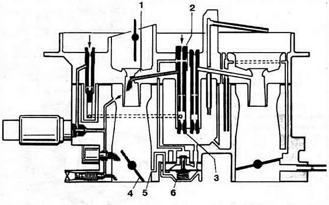
Fig. 2-38. Operation diagram of the main dosing system of the 1st chamber at partial load and the power mode economizer:
1 - small diffuser;
2 - main air jet;
3 - main fuel jet;
4 - throttle valve;
5 — economizer vacuum intake hole;
6 — power mode economizer.
Power mode economizer. The main metering system of the 1st chamber includes a power mode economizer, which is triggered at a certain vacuum behind the throttle valve of the 1st chamber. Fuel is taken from the float chamber through the diaphragm valve. As long as the diaphragm is held by the vacuum in the intake manifold, the valve is closed. When the throttle valve opens to a certain angle, the vacuum drops and the diaphragm of the valve opens under the action of the spring. An additional amount of fuel enters the emulsion tube of the main metering system of the 1st chamber through the channels. At the same time, the supply of additional emulsion through the gap of the transition system and the outlet opening of the idle system gradually stops. Transition system of the 2nd chamber. The throttle valve of the 2nd chamber remains blocked until the throttle valve of the 1st chamber opens to a certain angle. In this case, under the action of the vacuum, the pneumatic drive rod of the throttle valve of the 2nd chamber moves, ensuring its opening. The transition system operates until the main metering system of the 2nd chamber is switched on. The main metering system of the 2nd chamber and the economizer (Fig. 2-39). As the vacuum in the small diffuser zone drops, the amount of fuel-air emulsion formed in the main metering system of the 2nd chamber increases. At full load at speed modes close to maximum, with fully open throttle valves, the economizer is switched on. Fuel from the float chamber enters the fuel tube through the economizer nozzle and is sucked into the secondary mixing chamber through the injection tube, enriching the working mixture.
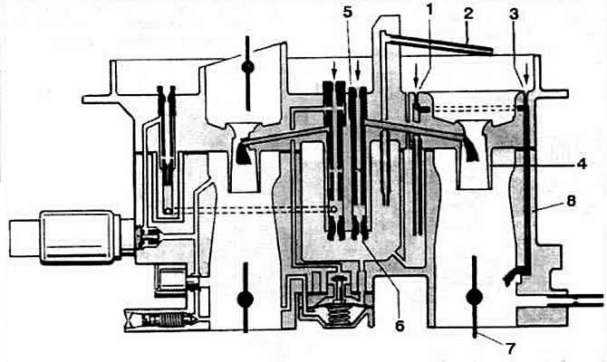
Fig. 2-39. Schematic diagram of the operation of the main dosing systems at full load and the economizer:
1 - ventilation hole;
2 - economizer injection tube;
3 — air jet of the transition system of the 2nd chamber;
4 - small diffuser;
5 - main air jet of the 2nd chamber;
6 - main fuel jet of the 2nd chamber;
7 — 2nd chamber throttle valve;
8 — channel of the transition system of the 2nd chamber.
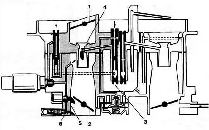
Fig. 2-35. Carburetor operation diagram when starting a cold engine:
1 - air damper;
2 - throttle valve;
3 - main fuel jet of the 1st chamber;
4 - small diffuser;
5 — transition system gap;
6 — idle system outlet.
Visitor comments