
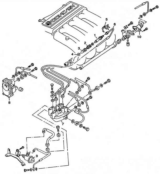
Pic. 2-156. Details of the engine fuel supply system «KR»:
1 - nozzle;
2 - body of the fuel injector;
3 - sleeve;
4 - sealing ring;
5 - clamp;
6 - fuel supply pipeline to the nozzle;
7 - dispenser-distributor of fuel;
8 - control pressure regulator;
9 - fuel pressure regulator;
10 - starting nozzle.
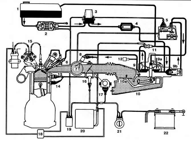
Pic. 2-157. Structural diagram of the fuel injection system «K-Jetronlc» engine «KR»:
1 - fuel tank;
2 - fuel pump;
3 - pressure accumulator;
4 - fuel filter;
5 - control pressure regulator;
6 - fuel injector;
7 - inlet pipeline;
8 - electromagnetic starting nozzle;
9 - mixture regulator;
9a - fuel distributor;
9b—fuel pressure regulator;
10 - air flow meter;
10a - pressure disk;
11 - solenoid valve forced idle;
12 - vacuum switch;
13 - thermal time relay;
14 - coolant temperature sensor;
15 - ignition distributor;
16 — the electromagnetic valve of stabilization of idling;
17 - throttle position sensor;
18 - electronic ignition timing control unit;
19 — the relay of inclusion of the fuel pump;
20 - electronic block for idling stabilization and forced idling control;
21 - ignition switch;
22 - battery.
The fuel pump takes fuel from the fuel tank and delivers it to the hydraulic accumulator. Further, the fuel is supplied under pressure through the filter to the fuel dispenser-distributor.
Mounted on a movable arm, the pressure plate of the air flow meter, which is installed between the air filter and the throttle valve, deviates depending on the air depression in the engine. The displacement of the pressure disk of the air flow meter is transmitted to the distribution plunger of the fuel dispenser, thereby determining the amount of fuel supplied. The fuel quantity distributor, depending on the position of the pressure plate of the air flow meter, supplies the required amount of fuel to the engine cylinders through the injectors, ensuring the optimal composition of the fuel-air mixture. The fuel dispenser and air flow meter form a mixture regulator. The pilot pressure regulator reduces pressure on the control plunger during engine warm-up. Reducing the control pressure at the same air flow leads to an increase in the fuel supply and, consequently, to an enrichment of the combustible mixture.
By commands of a special electronic control unit (ECU) idle speed solenoid valve installed in the air duct parallel to the throttle valve. brings additional air to the engine during cold start and engine warm-up, which leads to an increase in the engine speed at idle, and also ensures that the idle speed is maintained within the specified limits. The overrun fuel supply is interrupted by an electronically controlled solenoid valve.
To facilitate starting a cold engine, an electromagnetic starting nozzle is provided, the opening time of which varies depending on the temperature of the coolant by a thermal time switch. The plastic fuel tank is installed under the body floor in front of the rear axle. Fuel tank capacity 70 l. Air filter brand and type Mann C31 152 with a replaceable dry filter element.
The fuel filter is installed at the rear of the vehicle.
Brand and Part No.: Factory installed filter: Bosch 0 450 905 144; spare part filter: Bosch 0 450 905 143.
Replacement frequency: every 20,000 km of the vehicle run. The electric fuel pump is installed in a housing at the rear of the vehicle on the right.
Make and part number: factory installed pump: Bosch 0 580 254 012; spare parts pump: Bosch 0 580 254 011.
An electric fuel priming pump is installed in the fuel tank. Performance at a voltage of 12 V at the terminals, cm3/30 s: 300. Fuel dispenser mounted on the air flow meter. provides a uniform supply of fuel to the intake nozzles, depending on the position of the pressure plate of the air flow meter.
Brand and catalog number: Bosch 0 438 100 140. A pressure accumulator installed in the fuel supply line after the fuel pump maintains residual fuel pressure in the system after the engine has stopped and eliminates fuel supply fluctuations.
Make and part number: factory installed battery: Bosch 0 438 170 028; spare parts battery: Bosch 0 438 170 027.
The fuel pressure regulator installed in the fuel dispenser serves to maintain the fuel pressure within the specified limits.
The regulator regulates the control pressure depending on the temperature.
Make and part number: factory installed regulator: Bosch 0 438 140 141; spare parts regulator: Bosch 0 438 140 140.
The opening of the injector valves occurs under the influence of fuel pressure.
Make and part number: factory installed nozzles: Bosch 0 437 502 042; nozzles supplied as spare parts: Bosch 0 437 502 041.
The starting injector is used to enrich the mixture when starting a cold engine according to the signals of a thermal time relay.
Make and part number: factory installed nozzle: Bosch 0 280 170 407; nozzle supplied as spare parts: Bosch 0 280 170 406.
Thermal time switch. Make and part number: factory installed relay: Bosch 0 280 130 213; relay supplied as spare parts: Bosch 0 280 130 214. Air flow meter.
Make and Part No.: Factory installed meter. Bosch 0 438 120 196; spare part meter: Bosch 0 438 120 195.
A rotary idle stabilization solenoid valve is installed in the air duct parallel to the throttle valve. By commands of a special control unit, it provides an enrichment of the combustible mixture when starting a cold engine, and also serves to maintain the engine speed within the specified limits.
Brand and catalog number: Bosch 0 438 040 140. Control current, mA: 415-445.
The coolant temperature sensor is an NTC resistor. those. its resistance decreases with increasing temperature.
The sensor is installed on the end face of the cylinder head on the side of the ignition distributor. The signal from the sensor is fed to the electronic idle stabilization and forced idle control unit.
The vacuum switch installed on the air flow meter serves to enrich the mixture through the starting injector with a significant increase in engine load. Its contacts are open in normal mode and close with a sharp change in vacuum. A position type throttle position sensor is mounted on the throttle. The signal from the sensor is used to determine the mode of operation of the engine (idle or full throttle).
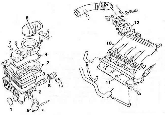
Pic. 2-158. Engine air path details «KR»:
1 - branch pipe for outside air intake;
2 - air filter housing;
3 - filter element;
4 - sealing gasket;
5 - air flow meter;
6 - air supply cap;
7 - electrical connector;
8 - heated air supply hose;
9 - thermostat;
10 — the top part of the inlet pipeline;
11 - the lower part of the intake pipeline;
12 - throttle body.
Visitor comments