
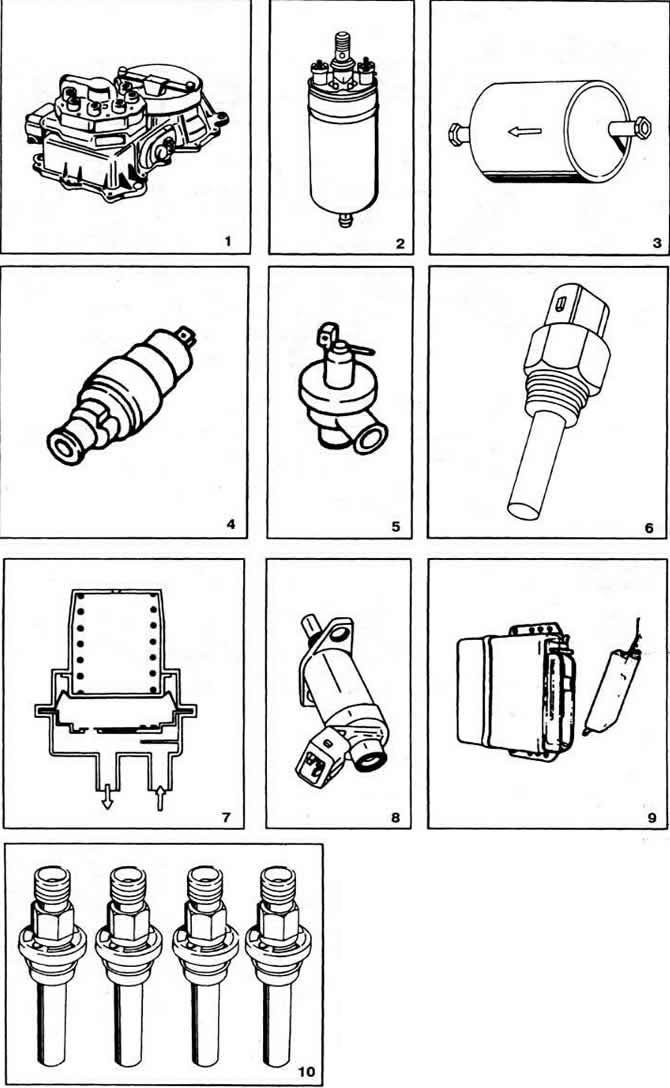
Pic. 2-159. Components of the fuel injection system «K-Jetronlc» engine «KR»:
1 - mixture regulator (assembly formed by a fuel dispenser and an air flow meter);
2 - fuel electric pump;
3 - fuel filter;
4 — the electromagnetic valve of stabilization of idling;
5 - shut-off valve of the adsorber;
6 - thermal time relay;
7 - pressure accumulator;
8 - starting nozzle;
9 - electronic block for idling stabilization and forced idling control;
10 - fuel injectors.
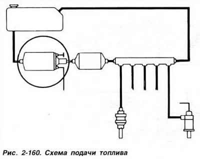
The fuel pump takes fuel from the fuel tank and delivers it through the filter and accumulator to the fuel distributor (pic. 2-160).
Fuel pump (pic. 2-161) roller. It is driven by a constant excitation electric motor. Along the circumference of the eccentric rotor mounted on the motor shaft, roller slots are made. Under the action of centrifugal force, the rollers are pressed against the pump housing, which ensures the tightness of the pump. The fuel sucked in through the gaps between the rollers enters the discharge line. The pump is explosion-proof, since a combustible mixture never forms in its casing. At all engine operating modes, the pump delivers an excess amount of fuel compared to the maximum amount of fuel required to maintain a constant pressure in the fuel supply system.
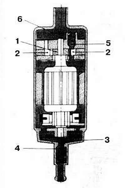
Pic. 2-161. Section of the fuel electric pump:
1 - rotor;
2 - rollers;
3 - discharge channel;
4 - check valve;
5 - overpressure valve;
6 - inlet chamber.
The pump is switched on by a relay. If the engine does not start or starts with difficulty, idles erratically, stalls regardless of the mode of operation, and also does not develop full power, then a fuel pump malfunction may be the cause.
The amount of air sucked into the intake manifold is measured by an air flow meter.
The air flow meter is installed in front of the throttle valve. It is a guiding device with a pressure disc mounted on a movable lever, which deviates depending on the air flow (pic. 2-162). The displacement of the pressure plate of the air flow meter is transmitted through the lever to the distributor plunger, which determines the amount of fuel in the system.
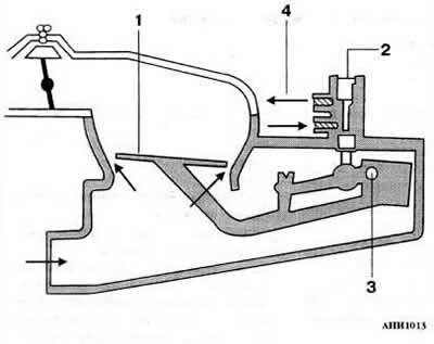
Pic. 2-162. The principle of operation of the air flow meter:
1 - pressure disk;
2 - distribution plunger;
3 - axis of the lever;
4 - to the intake valves.
As part of the fuel quantity distributor. except for the distributor plunger. includes fuel pressure regulator, differential pressure valves, supply line and four injection nozzles according to the number of engine cylinders (pic. 2-163). When the pressure plate of the air flow meter is raised, the distributing plunger of the fuel quantity distributor moves accordingly, opening its control edges for fuel access to the upper chamber of the differential pressure valve, separated from the lower chamber by a diaphragm. The fuel pressure and the force of the spring acting on the upper surface of the diaphragm are greater than the pressure on the lower surface of the diaphragm. As a result of this, the diaphragm moves down and opens the channels for supplying fuel to the injectors (pic. 2-165). Difficult start, inability to start the engine, as well as its unstable idling, indicate a possible malfunction of the injectors. The fuel pressure regulator maintains the fuel pressure in the system at a certain level and ensures that excess fuel is supplied to the drain line (pic. 2-166).
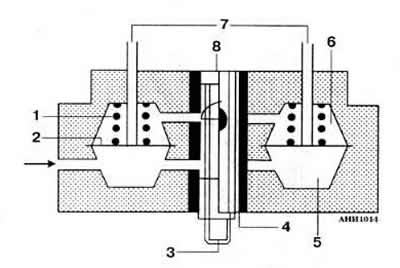
Pic. 2-163. The principle of operation of the dispenser-distributor of fuel:
1 - valve spring;
2 - diaphragm;
3 - distribution plunger;
4 - slotted sleeve of the distribution plunger;
5 - lower chamber;
6 - upper chamber;
7 - fuel supply to the nozzles;
8 - control edge of the distribution plunger.
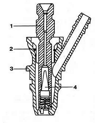
Pic. 2-165. Injection nozzle section:
1 - sprayer body;
2 - sealing ring;
3 - nozzle body;
4 - conical filter.
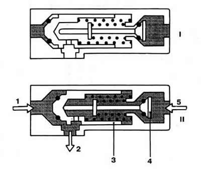
Pic. 2-166. The principle of operation of the fuel pressure regulator:
I - non-working position;
II - working position.
1 - fuel supply under supply pressure;
2 - fuel outlet to the fuel tank;
3 - plunger of the supply pressure regulator;
4 - uncoupling valve;
5 - from the control pressure regulator.
The fuel filter is designed to clean the fuel circulating in the system. The arrow on the filter housing shows the direction of fuel flow in the system.
The pressure accumulator is mounted behind the fuel pump (pic. 2-167). It has damper and accumulative chambers, which are separated by a diaphragm. In front of the diaphragm there is an additional partition with a disc valve that provides fuel supply to the system. A throttling hole for draining fuel is made in the partition.
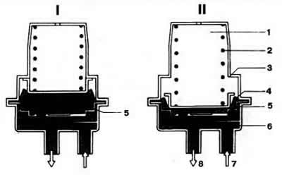
Pic. 2-167. How the pressure accumulator works:
I - with the engine running;
II - with the engine stopped.
1 - sleeve;
2 - spring;
3 - emphasis;
4 - diaphragm;
5 - storage chamber;
6 - reflector;
7 - fuel supply;
8 - fuel outlet.
After turning on the fuel pump, the storage chamber is filled with fuel and the spring diaphragm is stretched to the stop. When the engine is stopped, the tension of the diaphragm keeps the fuel under pressure and prevents the formation of fuel vapors, which makes it easier to start a hot engine.
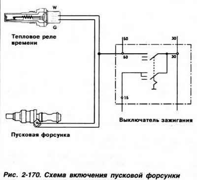
Starting and warming up of the engine is provided by an electromagnetic starting nozzle, an additional air supply valve and a control pressure regulator. Electromagnetic starting nozzle (pic. 2-168) designed to inject additional fuel into the intake manifold at the time of starting a cold engine. It works in conjunction with a thermal time relay (pic. 2-169), which closes and opens it with an electrical circuit, depending on the temperature of the engine and the duration of its start (pic. 2-170).
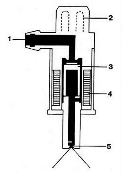
Pic. 2-168. Injector section:
1 - fuel supply pipe;
2 - block;
3 - magnetic core;
4 - winding;
5 - swirl atomizer.
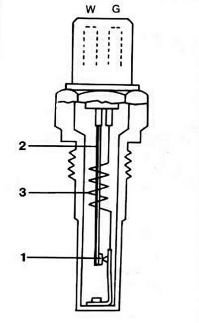
Pic. 2-169. Section of the thermal time relay:
1 - contact;
2 - bimetallic spring;
3 - thermal winding.
Difficulty starting or inability to start the engine, as well as increased fuel consumption, may be caused by a malfunction of the starting injector. If the engine does not start or runs erratically at idle, a faulty thermal time relay may be the cause.
The sensor mounted on the throttle valve shaft has two switching contacts for both end positions of the throttle valve. On throttle axis 3 (pic. 2-171) The sensor has a movable contact 2, which, in accordance with the position of the throttle valve, closes and opens contact 4 at idle or contact 1 at full load. When closed (idling) or wide open throttle (full load) the corresponding signals are sent to the idle stabilization and forced idle control unit. which, on their basis, generates commands for the solenoid valves for stabilizing idling and forced idling. The idle speed solenoid valve serves to increase the crankshaft speed during engine warm-up, and also ensures that the idle speed is maintained within the specified limits. The valve is installed in an air duct parallel to the throttle valve. The degree of its discovery, i.e. the amount of additional air entering the engine intake tract is determined by the electronic idle stabilization and forced idle control unit.
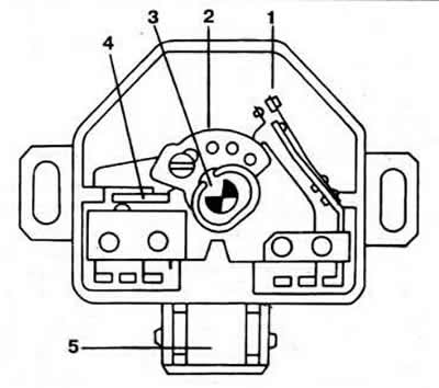
Pic. 2-171. Throttle Position Sensor:
1 - full load contact;
2 - moving contact;
3 - throttle axis;
4 - idle contact;
5 - block.
In addition, the supply of additional air is measured by the pressure disc of the air quantity meter (pic. 2-172), the movement of which leads to a corresponding rise in the distribution plunger, which also contributes to an increase in the crankshaft speed (with closed throttle). The control pressure regulator enriches the working mixture entering the combustion chambers when the engine warms up (pic. 2-166). On a cold engine, the bimetal spring compresses the diaphragm valve spring, opening the fuel drain channel, which leads to a decrease in resistance on the distribution plunger. A decrease in control pressure at a constant air flow causes an increase in the stroke of the pressure disc. As a result, the distribution plunger is additionally raised, increasing the amount of fuel supplied to the injectors.
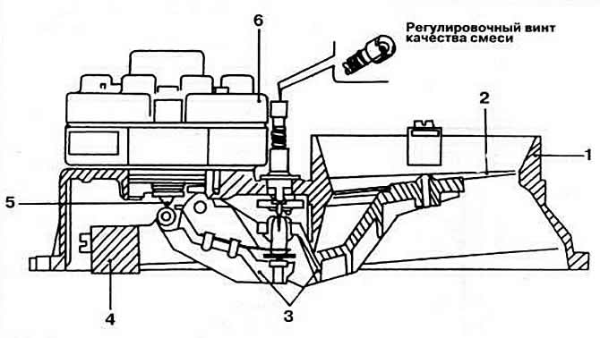
Pic. 2-172. Cross section of the mixture regulator:
1 - diffuser of the air flow meter;
2 - pressure disk;
3 - system of levers;
4 - counterweight;
5 - distribution plunger;
6 — dispenser-distributor of fuel.
As the bimetal spring heats up, the pressure on the diaphragm valve spring of the control pressure regulator decreases and the drain channel slowly closes. The control pressure reaches a normal value and the enrichment of the combustible mixture stops.
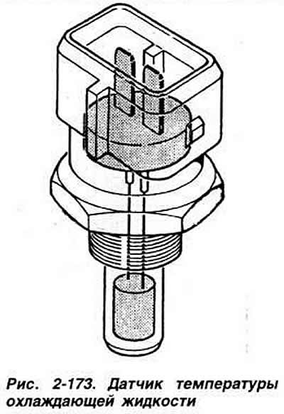
While the engine is warming up, the idle speed stabilization and forced idle control unit provides an enrichment of the combustible mixture based on an electrical signal from the coolant temperature sensor installed in the cylinder head.
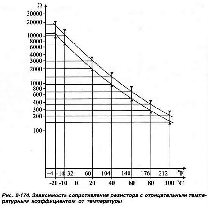
Sensor (pic. 2-173) is a resistor with a negative temperature coefficient, i.e. resistance decreases as temperature rises (see graph, fig. 2-174). If the engine does not start or starts with difficulty. stalls after starting, as well as with increased fuel consumption and abnormal CO content in the exhaust gases. it is necessary to check the serviceability of the coolant temperature sensor.
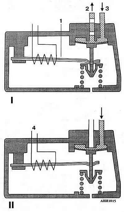
Pic. 2-164. Operating principle of the control pressure regulator:
I - on a cold engine;
II - on a hot engine.
1 - bimetallic spring;
2 - fuel drain;
3 - control pressure supply;
4 - thermal winding of a bimetallic spring.
Visitor comments