
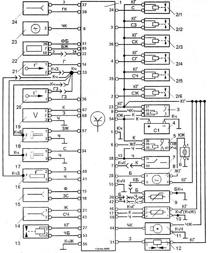
Pic. 21. The electrical circuit of the fuel injection control subsystem KSUD «Motronic» engine «AAA» car «Passat 2,8 VR6»: 1 - controller; 2/1-6 - nozzles: 3 - power relay; 4 - battery; 5 — the relay of inclusion of the fuel pump; 6 - fuel pump; 7 - ignition switch; 8 - EB of the system for monitoring the oxygen content in the exhaust gases; 9 - oxygen content sensor in exhaust gases; 10 - mass air flow meter; 11 - sparking moment sensor: 12 - adsorber purge solenoid valve: 13 - idle speed controller; 14 - diagnostic block: 15 - engine compartment wiring harness connector; 16 - potentiometric throttle position sensor; 17 - sensor I detonation; 18 - knock sensor II; 19 - crankshaft speed sensor; 20—intake air temperature sensor: 21—coolant temperature sensor; 22 - on-board computer; 23 - switch: 24 - air conditioner connector; PV - fusible link.
Wire color designation: B - white: D - blue; W - yellow: 3 - green: K - red; Kch - brown; C - gray: F - purple; H - black.
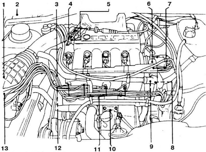
Pic. 23. Placement on the car of elements of the fuel injection system «KE-Jetronic» engine «PL»: 1 - air flow meter: 2 - ECU: 3 - forced idle valve: 4 - throttle body; 5 - idle and full load switches; 6 - idle speed regulator: 7 - fuel pressure regulator; 8 - coolant temperature sensor; 9 - thermal time relay: 10 - control pressure regulator; 11 - injection nozzles; 12 - starting nozzle: 13 - fuel dispenser.
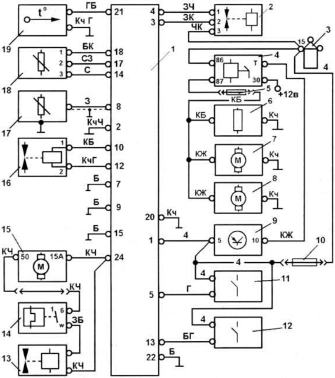
Pic. 28. Electrical diagram of the fuel injection system «KE-Jetronic» engine «PL» car «Passat 16V Cat»: 1 - ECU fuel injection; 2 - idle speed regulator; 3 - ignition coil; 4 —relay for turning on the fuel pump; 5 - fuse No. 5; 6 - oxygen sensor heater; 7 - fuel pump: 8 - fuel priming pump; 9 - ECU ignition delay; 10 - fuse No. 17; 11 - full load switch; 12 - idle switch; 13 - control pressure regulator; 14 - thermal time relay: 15 - starter; 16 - fuel pressure regulator; 17 - oxygen content sensor in exhaust gases; 18 - air flow meter; 19 - coolant temperature sensor.
The color designation of the wires is shown in fig. 21, no color designation indicates internal connection (e.g. connection to housing or connection via PCB).
NOTE: The following is a description of only those checks and adjustments, the procedure for which differs from that described for the fuel injection system «K-Jetronic» engine «KR» (see section «16 valve engines»).
Checking and adjusting the engine idle
These operations are carried out in the same way as on the engine «KR» with injection system «K-Jetronic» (see section «16 valve engines»), except for the following.
Before checking, it is necessary to make sure that the oxygen content sensor in the exhaust gases is working. Checking the idle speed (800-900 rpm) performed after the engine has changed from fast idle to normal idle. The content of CO in the exhaust gases should be within 0.3-1.2%.
Idle switch adjustment
Connect the VAG 1501 test cord to the switch wires and to the multi-pin connector.
Connect one wire of the voltmeter to wire No. 1 of the test cord, and connect the other wire of the voltmeter to «weight» (pic. 20).
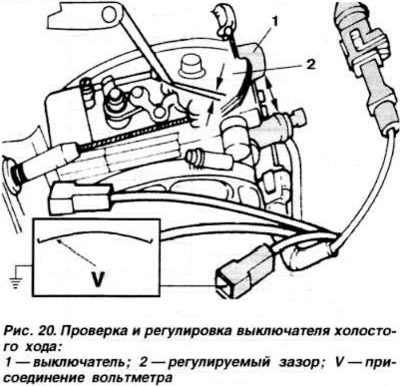
Switch on the ignition In this case, the voltmeter should show the voltage of the battery.
Open and close the throttle until the throttle lever touches the stop screw.
Insert a feeler gauge 0.15-0.5 mm thick between the lever and the stop and make sure that that when the throttle is moved, the switch is activated.
If the circuit breaker does not operate, loosen the screws securing the circuit breaker and achieve operation by shifting the body of the circuit breaker. then tighten the fixing screws.
Full load switch adjustment
Connect the VAG 1501 test cord to the throttle switch wires and to the multi-pin connector Connect one voltmeter wire to wire No. 3 of the test cord, and connect the other voltmeter wire to «weight» (pic. 22).
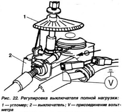
Fully open throttle. In this case, the voltmeter should show the voltage of the battery. Fasten the goniometer 1 to the throttle shaft and, with the throttle valve fully open, set the goniometer needle to zero.
Close the throttle valve about 20°on the goniometer, then open it again until the switch operates. The switch should operate 10±2°before full throttle position.
In case of deviation from the specified norm, loosen the screws securing the circuit breaker body and adjust the actuation torque within the specified limits by shifting it, then tighten the fastening screws.
Checking the supply voltage of switches
Connect the VAG 1501 test cord to the switch wires and to the multi-pin connector.
Connect one wire of the voltmeter to wire No. 2 of the test cord, and connect the other wire of the voltmeter to «weight». In this case, the voltmeter should show the voltage of the battery.
Fuel pressure check
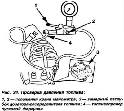
Connect the pressure gauge to the measuring pipe 3 of the fuel dispenser (pic. 24) and to the fuel line 4 starting injectors.
Connect the remote control unit VAG 1348 / ZA to the previously disconnected connector of the oxygen content sensor in the exhaust gases and to «+» battery.
Open the valve 2 of the manometer, turn on the remote control unit and check the manometer readings, which should be within 5.2-5.6 kgf / cm2.
Control pressure test
Connect pressure gauge and remote control as above.
Connect test cord VAG 1251 A/1 to differential pressure regulator. Connect a voltmeter to the test lead.
Close valve 1 manometer.
Disconnect the pilot pressure regulator connector and turn on the remote control. In this case, the control pressure should be set to 0.2-0.5 kgf / cm2 below the fuel pressure in the system.
Disconnect the thin hose from the pressure regulator and lower the end of the hose into a beaker.
Connect the control pressure regulator connector. Turn on the remote control unit for 1 minute and measure the amount of fuel poured into the beaker, which should be within 130-150 cm3.
Attach a thin hose to the pressure regulator. Disconnect the coolant temperature sensor connector. Connect the coupled adapter with the 15 kΩ resistance side to the disconnected multi-pin connector. Connect the control pressure regulator connector and switch on the ignition. In this case, the pressure gauge should show the steady pressure, which should be 0.7-1.2 kgf / cm2 higher fuel pressure in the system. In this case, the control current should be within 50-70 mA.
Checking and adjusting the position of the pressure plate of the air flow meter
Warm up the engine (oil temperature above 50°C). Crank the crankshaft with the starter for 10 s. Check the position of the pressure plate of the air flow meter. In the initial position of the pressure disk, the upper edge of its edge should be 1.9 + 1.1 mm below the beginning of the expanding cone of the air flow meter housing (size A in fig. 25).
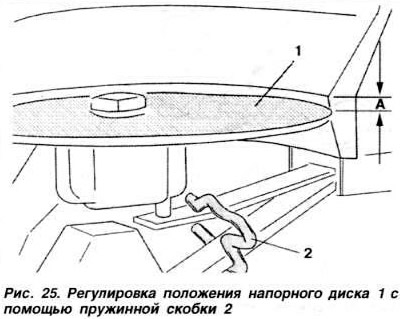
In case of deviation from the norm, raise the pressure disc and adjust its position within the specified limits by straightening or bending the spring bracket 2. In this case, it is forbidden to bend the leaf spring of the disc stop.
At the end of the adjustment, check and, if necessary, adjust the idle speed of the engine.
Exhaust oxygen sensor test
Warm up the engine to normal operating temperature and let it idle for at least 2 minutes.
Check carbon monoxide content (SO) in exhaust gases. then pinch the crankcase ventilation hose. In this case, the CO content should first increase briefly, then decrease to its original value
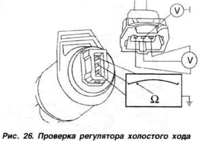
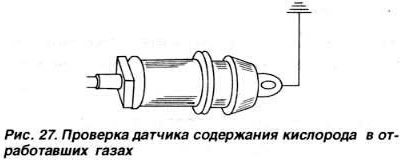
If the CO content does not decrease, disconnect the connector of the oxygen content sensor in the exhaust gases and connect to «weight» connector wire. going to the controller (pic. 27). If the CO content does not change after about 20 seconds, replace the oxygen sensor.
Checking the enrichment of the mixture during acceleration
Using the VAG 1315 A/1 test cord, connect the digital multimeter to the pilot pressure regulator.
Disconnect the coolant temperature sensor connector.
Disconnect the air supply hood from the air flow meter.
Turn on the ignition.
Open the throttle valve about 1/3 of its travel. The ammeter should show a current of 80-100 mA.
Move the pressure disk of the air flow meter sharply upwards. In this case, the current on the ammeter should briefly increase to a value of more than 100 mA.
Checking the enrichment of the mixture when restarting and warming up the engine
Disconnect the high voltage wire from the ignition distributor and connect to «weight» through an extension. Connect the universal digital measuring device to the control pressure regulator using the test cord VAG 1315 A/1.
Disconnect the coolant temperature sensor connector.
Turn on the starter for about 2 seconds and leave the ignition on. In this case, the ammeter readings should be more than 120 mA for 30-60 s, then drop to 80-100 mA within 20-50 s.
Full load richness test
Using the test cord VAG 1315 A/1, connect the universal digital measuring device to the control pressure regulator.
Disconnect the coolant temperature sensor connector and connect the VAG 1490 twin adapter to the connector. Start the engine and increase the engine speed to 2500 rpm.
When the full load switch trips, the ammeter should show a current of about 16 mA.
Checking the electrical circuits of the system «KE-Jetronic» through the ECU connector
Switch off the ignition.
Disconnect the ECU connector.
Disconnect the high voltage wire from the ignition distributor and connect it to «weight».
For checks, use a universal digital low impedance meter.
Visitor comments