
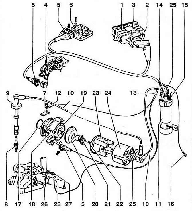
Pic. 2-196. Details of the engine ignition system «KR»:
1 - electronic ignition timing control unit;
2 - connecting block of the block;
3 - vacuum hose fitting;
4 - throttle position sensor;
5 - connecting blocks;
6 - switch;
7 - locking plate;
8 - spark plug;
9 - holder;
10 - high-voltage wire;
11 - ignition coil;
12, 16, 28 - wire terminal;
13, 25 - tip;
14 - high-voltage wire socket;
15 - positive contact;
17 - stuffing box;
18 — the screw of fastening of the case of the distributor of ignition;
19 - ignition distributor;
20 - protective screen;
21 - rotor;
22 - coal;
23 - cover;
24 - noise suppression screen;
26 - sealing ring;
27 - coolant temperature sensor.
The microprocessor control unit, in accordance with the programmed program, automatically optimizes the ignition timing depending on the ignition mode. The ignition system includes: an electronic ignition timing control unit with a built-in vacuum sensor; ignition distributor with built-in Hall sensor; switch; ignition coil; spark plug.
The electronic ignition timing control unit is installed in the engine compartment, on the bulkhead shield amplifier, on the right. Provides software control of the ignition timing depending on the number of revolutions and engine load and coolant temperature. After processing the signals, the unit outputs control signals to the switch to the primary winding of the ignition coil and through it to the secondary winding of the ignition coil, thus determining with high accuracy the moments of current interruption in the primary winding and supplying a high-load current through the ignition distributor to the spark plug of the corresponding cylinder, depending on the value of the ignition timing stored in the block memory. After that, the unit again issues a command to the switch to apply voltage to the primary winding of the ignition coil at a precisely defined moment in the engine's operating cycle. This process is repeated, however, at the same time, the time intervals for interrupting the current in the primary winding of the ignition coil are constantly changing depending on the information received by the control unit.
Thus, the ignition timing is automatically optimized depending on the engine operating mode. Distributor (pic. 2-197) driven by the intake camshaft. Direction of rotation right (when viewed from the drive side of the gas distribution mechanism). The Hall sensor integrated in the distributor performs the function of an engine speed sensor. Brand and catalog number: Bosch 027 906 205 R. Adjusting ignition timing to TDC at idle with a hose connected to the vacuum sensor 5-7°.
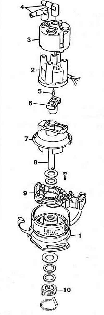
Pic. 2-197. Ignition Distributor Details:
1 - distributor housing;
2 - cover;
3 - noise suppression screen;
4 - interference suppression tip;
5 - coal;
6 - distributor rotor;
7 - protective screen;
8 - drive shaft;
9 - Hall sensor;
10 - clutch.
Ignition coil. Make and part number: factory installed coil: Bosch 0 221 122 400; coil supplied as spare parts: Bosch 0 221 122 399.
The resistance of the primary winding at 20°C is 0.6-0.8 Ohm. The resistance of the secondary winding at 20°C is 6.5-8.5 kOhm.
Spark plug. Brand and type: Bosch F6 DTC. Champion C6 BYC or Bern 14F 6DTU. The gap between the electrodes is 0.7-0.9 mm.
Elements for suppressing radio interference. Resistor in the rotor of the ignition distributor with a resistance of 0.6-1.4 kOhm, an interference suppression resistor with a resistance of 0.6-1.4 kOhm in the tip of the wire going to the ignition coil, resistors with a resistance of 4-6 kOhm in the tips of high-voltage wires from the side of the spark plugs.
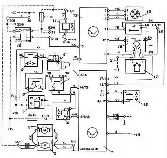
Pic. 2-195. Schematic diagram of the fuel injection system «K-Jetronic» engine «KR»:
1 - idle stabilization and forced idle control unit;
2 - fuel pump;
3 - fuel priming pump;
4 - solenoid valve forced idle;
5 - thermal time relay;
6 - vacuum switch;
7 - throttle position sensor (x.x. - idle, p.d. - full throttle);
8 - starter;
9 - starting nozzle;
10 — the relay of inclusion of the fuel pump;
11 - control pressure regulator;
12 - control unit of the ignition system;
13 - sensor-distributor ignition;
14 - coolant temperature sensor;
15 - wire to the tachometer;
16 - ignition switch;
17 - ignition coil;
18 — the electromagnetic valve of stabilization of idling;
19 - to the air conditioner.
See fig. for wire color designation. 2-96
Visitor comments