
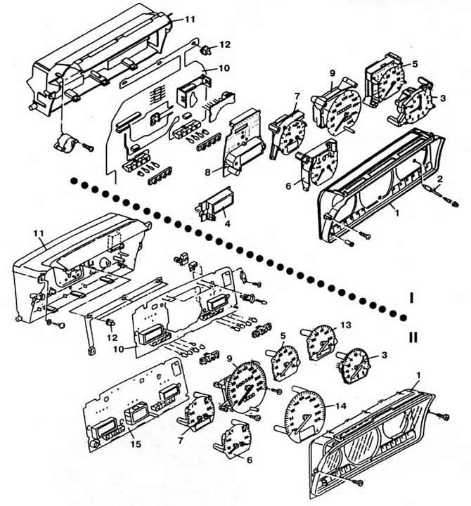
Pic. 8-18. Instrument cluster details:
I - cars up to 1989 model year;
II - cars from 1990 model year.
1 - visor;
2 - time setting button;
3 - pointer clock;
4 - digital clock (on some vehicles);
5 - tachometer;
6 - fuel level and coolant temperature gauges;
7 - fuel level and coolant temperature gauges on vehicles with a tachometer;
8 — trip computer monitor;
9 — speedometer with distance meters;
10 - printed circuit board;
11 - instrument panel housing;
12 - backlight;
13 — a tachometer of cars with an automatic transmission;
14 — speedometer of cars with a trip computer;
15 - computer circuit board.
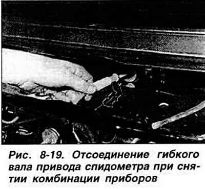
To remove, disconnect the cable from the negative battery terminal. Shine the facing of the horn button. Loosen the steering wheel nut and remove the steering wheel. Remove the instrument cluster visor by unscrewing the two fixing screws (pic. 8-22). Loosen the two screws securing the instrument cluster. Pull forward the right side of the instrument cluster and disconnect the electrical connectors from it, the flexible shaft of the speedometer drive (pic. 8-19) and, depending on the configuration, the tube of the vacuum fuel flow sensor. Remove instrument cluster.
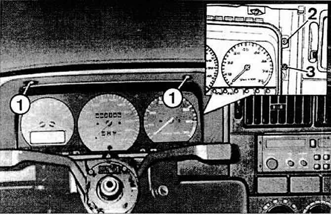
Pic. 8-22. Removing the instrument cluster:
1 - screws for fastening the visor;
2 — screws of fastening of a combination of devices;
3 — glass fastening screws.
To install, disconnect the flexible shaft of the speedometer drive from the mounting on the front panel of the body, pull the shaft into the passenger compartment and attach it to the socket in the instrument cluster. Install the instrument cluster in the reverse order of removal. After installation, make sure that all instruments and control lamps are working, and then during a test drive, check the correct position of the steering wheel and the operation of the speedometer.
Visitor comments