
English Русский
Български
Беларускі
Український
Српски
Hrvatski
Română
Polski
Slovenský
Magyar
  |  Articles  |  Sitemap  |  Contacts  |    |
Car maintenance Ford Car maintenance Hyundai Car maintenance Chevrolet Car maintenance BMW Car maintenance Audi Car maintenance Opel Car maintenance AvtoVAZ
VWmanual.ru


Main   Passat   Golf   Polo   Touareg   Tiguan   Sharan   Transporter   Others  
Transporter T3 (1979-1992) Transporter T4 (1990-2003)

Control devices — removal and installation (VW Transporter T4)

  • Main
  • Transporter
  • Transporter T4
  • Electrical equipment
  • Equipment and devices
  • Control devices — removal and installation
            0


Contents: Removal ↓ Installation ↓

Directional instruments
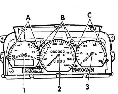


Directional instruments


The controls can be removed forward after removing the visor without the instrument cluster.

Removal


1. Disconnect the ground (-) cable from the battery.

Attention! This will erase the anti-theft code from the radio receiver's memory. Disconnect the battery only when the ignition is off. Otherwise, the injection system control unit will fail.


2. Remove the instrument visor (see subsection 10.19.8.1).

3. Instruments (1) and (3) are simply inserted and pulled out of the panel forward.

4. If it is necessary to remove the speedometer (2), remove the speedometer shaft behind the instrument panel, squeezing the plastic clutch on the sides. Unscrew the screws (B) and remove the speedometer.

Installation


1. Install the devices, make sure that the plugs on the back of the devices fit precisely into the plug contacts of the printed circuit board.

2. Screw on the speedometer, connect the speedometer shaft.

3. Install the instrument visor.

4. Connect the ground (-) cable to the battery.

Attention! Connect the battery only when the ignition is off, otherwise the injection system control unit may fail.


5. Set the time on the clock.

6. Enter the anti-theft code into the radio.

This article is available at russian, bulgarian, belarusian, ukrainian, serbian, croatian, romanian, polish, slovak, hungarian
The text has been checked: Orlov Dmitry

Share information:

Previous articles
Voltage stabilizer — removal, testing and installation
Testing LEDs
Control lamps — removal and installation
Replacing fuses
Rear Window Heated — Description and Testing
Sound signal — description and verification
Next articles
Speedometer shaft — removal and installation
Instrument cluster — design description
Instrument visor (dashboard) on the instrument panel
Steering Wheel Combination Switch — Design Description
Removal and installation the steering wheel combination switch
Connections on the combination steering wheel switch and steering lock


Similar articles from other manuals for VW cars:
Control devices Passat B5 (1996-2005)
Control devices Golf 4 (1997-2004)
Location of switches, instruments and control levers Polo 3 (1995-2003)
Control devices Touareg 1 (2002-2006)
Overview of control devices Tiguan 1 (2007-2015)
Electronic control unit — general information Sharan 1 (1995-2000)
Multifunction display (MFD) control Caddy 3 (2003-2010)
Link to this page in different formats


Visitor comments


No comments yet


How much will 26 + 30 =


Transporter T4 
  • General information
  • User manual
  • Maintenance
  • Power unit
  • Engine repair
  • Ignition system
  • Lubrication system
  • Cooling system
  • Fuel system (petrol)
  • Fuel system (diesel)
  • Injection system (petrol)
  • Exhaust system
  • Transmission
  • Clutch
  • Car gearbox
  • Chassis
  • Car suspension
  • Steering
  • Brake system
  • Wheels and tires
  • Body
  • Exterior
  • Interior
  • Doors and windows
  • Heating system
  • Electrical equipment
  • Equipment and devices
  • Lighting and signaling
  • Power devices
  • Electrical circuits
Transporter T3 
  • General information
  • Maintenance
  • Petrol engines
  • Engine repair
  • Lubrication system
  • Cooling system
  • Power and exhaust system
  • Carburetor 34 PICT
  • Carburetors 2E3 and 2E4
  • Fuel injection system
  • Ignition system
  • Diesel engines
  • Engine repair
  • Lubrication system
  • Cooling system
  • Power and exhaust system
  • Transmission
  • Clutch
  • Car gearbox
  • Chassis
  • Front suspension
  • Rear suspension
  • Steering
  • Brake system
  • Body
  • Body and interior elements
  • Doors, locks and windows
  • Electrical equipment
  • Lighting system
  • Equipment and devices
  • Power devices (diesel)
  • Power devices (petrol)
  • Wiring diagrams (diesel)
  • Wiring diagrams (petrol)
VWmanual.ru © 2016-2026 | Mobile version | News and articles | Sitemap: EN BG BY UA RS HR RO PL SK HU | Write message | Site search
Passat B2 • Passat B3 • Passat B4 • Passat B5 • Passat B6 • Golf 1, diesel • Golf 1, petrol • Golf 2, petrol • Golf 2 • Golf 3 • Golf 4 • Golf 5 • Polo 3 • Polo 4 • Touareg 1 • Tiguan 1 • Sharan 1 • Transporter T3 • Transporter T4 • LT 28 • LT 2D • Beetle • Caddy 3 •
Our website uses cookies to ensure functionality and convenience.