
Checking the stabilizer
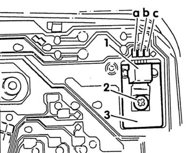
1. Voltage stabilizer; 2. Mounting screw; 3. Radiator
The stabilizer maintains a constant voltage on the devices. The stabilizer must be checked if the coolant temperature and fuel gauges give incorrect values.
Examination
1. Remove the visor and instrument panel cover.
2. Remove left instrument.
Attention! Do not disconnect the battery.
Attention! Instrument clusters with analog clocks or tachometers have a voltage stabilizer in a bezel on the circuit board behind the right gauge.
3. Turn on the ignition.
Input voltage test
4. Connect a voltmeter to the positive input (terminal 15) (A) and mass (b). Required value: approx. battery voltage (12 V). Otherwise, find a break in the wiring diagram.
Checking the output voltage
5. Connect a voltmeter to the output pole (With) and mass (b). Required value: 9.5-10.5 V, otherwise, a break in the conductive foil or the voltage regulator is faulty. Replace defective part.
Attention! The conductive foil cannot be replaced separately. The entire instrument panel is being replaced.
Removing
1. Switch off the ignition.
2. Unscrew the fastening screw (2) and pull down from the contacts (a, b, c) Voltage regulator.
Installation
1. Set the three connections correctly to the contacts (a, b, c).
2. Screw the voltage stabilizer securely to the heatsink. Radiator (3) serves to remove the heat generated during operation. Therefore, without a radiator, the stabilizer should not be installed.
Visitor comments