
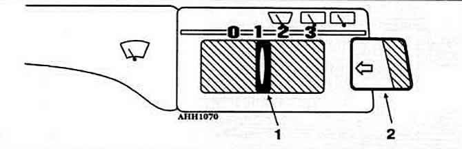
Pic. 8-17. On-board computer control switch:
1 - switch for selecting the type of information and resetting indications;
2 - key for sequential output of information to the monitor.
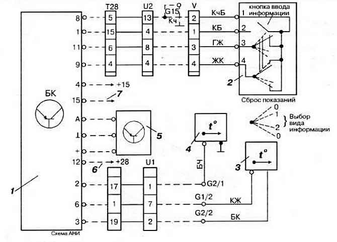
Pic. 8-20. Scheme of switching on the on-board computer:
1 - on-board computer;
2 - block of computer switches;
3 - outdoor air temperature sensor;
4 - oil temperature sensor;
5 - air flow sensor;
6 - to the speed sensor;
7 - to the tachometer.
See fig. for wire color designation. 8-8.
The computer has two storage devices. into which the following information is entered.
1. In the memory of the current information used at the position «1» switch slider:
- duration of the trip in hours and minutes. not counting the time of stops;
- average fuel consumption in l/100 km;
- distance traveled in km;
- average speed in km/h.
Note. If the vehicle stops for more than 2 hours, this information is automatically deleted.
2. Summing memory. used in position «2» switch slider, displays the listed types of information, as well as their total values stored until the following limit values are reached:
- driving time: 100 h;
- distance traveled 10,000 km;
- fuel consumption: 1000 l
Regardless of both memories, the following current information is output:
- engine oil temperature within 50-160°C;
- outside air temperature in the range from -40 to +50°С.
Note. Fuel flow sensor that senses vacuum in the engine intake manifold and speed sensor (Hall Sensor) located behind the instrument cluster. The location of the computer connectors is given in fig. 8-21.
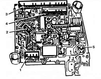
Pic. 8-21. Location of on-board computer connectors:
1 - 4-pin connector of an electronic clock;
2 - 3-pin connector of the fuel consumption sensor;
3 - 8-pin connector for fuel and temperature gauges;
4 - 5-pin connector;
5 - backlight.
Visitor comments