
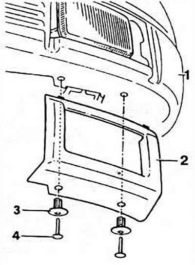
Pic. 8-13. Removing fog lights:
1 - front bumper;
2 — facing of a headlight;
3 - fastening pin;
4 - spacer sleeve.
Instrument cluster
The instrument cluster of the brand VDO or Moto Meter is made on printed circuits on a flexible board.
In the lower part of the instrument cluster there are control lamps for oil pressure, switching on the main beam of headlights. direction indicators, brake fluid level and parking brake activation, battery charging, fuel injection system malfunctions (depending on the model).
Note. The ABS brake warning lamp is located on the instrument panel to the left of the light switch. and the coolant temperature warning light is built into the coolant temperature gauge.
The instrument cluster includes a coolant temperature gauge, a fuel gauge with a 10-liter fuel remaining sector, a digital clock, an electronic speedometer with a summing and daily distance counter and a tachometer. Details of a combination of devices and purpose of conclusions of a socket of a combination of devices see on fig. 8-18 and 8-16.
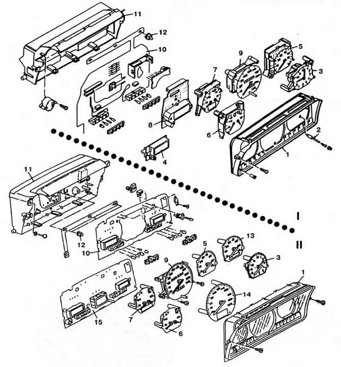
Pic. 8-18. Instrument cluster details:
I - cars up to 1989 model year;
II - cars from 1990 model year.
1 - visor;
2 - time setting button;
3 - pointer clock;
4 - digital clock (on some vehicles);
5 - tachometer;
6 - fuel level and coolant temperature gauges;
7 - fuel level and coolant temperature gauges on vehicles with a tachometer;
8 — trip computer monitor;
9 — speedometer with distance meters;
10 - printed circuit board;
11 - instrument panel housing;
12 - backlight;
13 — a tachometer of cars with an automatic transmission;
14 — speedometer of cars with a trip computer;
15 - computer circuit board.
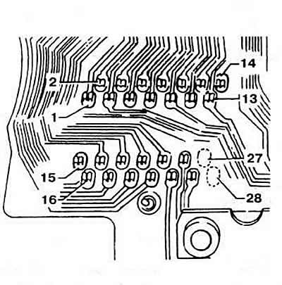
Pic. 8-16. Pin assignment of the 28-pin connector of the instrument cluster:
1 - connection output with «weight» outdoor temperature sensor (for on-board computer);
2 - reserve;
3 - output «31» on «mass»;
4 - output to the on-board computer control switch (reset information);
5 - output «31» - connection with «weight» on-board computer;
6 - output to the on-board computer control switch (choice of information type);
7 - output for the signal of the speed sensor;
8 - output for the signal of the oil pressure sensor, calibrated at 1.8 kgf / cm2;
9 - output for the signal of the oil pressure sensor, calibrated to 0.3 kgf / cm2;
10 - output for the tachometer signal;
11 — «+» battery;
12— «+» lighting circuits;
13 — «+» ignition or instrument switch and starter;
14 - reserve;
15 - output to the computer control switch (information run);
16 - output to the control lamp charging the battery;
17 - output to the computer oil temperature sensor;
18 - output to the control lamp of the level of the brake fluid and the inclusion of the parking brake;
19 - output for the outside air temperature signal supplied to the computer;
20 - reserve for the diesel starting heating system;
21 - output to the fuel gauge;
22 - output to the control lamp of a malfunction of the fuel injection system;
23 - output to the coolant temperature gauge;
24 - output to the control lamp direction indicators;
25 - output to the control lamp for turning on the high beam headlights;
26 - reserve;
27, 28 - unattached conclusions.
Note
1. On some cars, the supply voltage of the devices is regulated by a voltage stabilizer in the range of 9.75-10.25.
2. When the ignition or instruments are turned on, the coolant temperature warning lamp flashes several times, indicating that it is working.
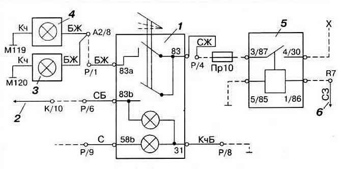
Pic. 8-9. Scheme of inclusion of fog lamps and rear fog lamp
1 — the switch of antifog headlights and lanterns;
2 - to fog lamps;
3 - right fog lamp;
4 - left fog lamp;
5 - power relay for fog lights and lamps;
6 - to the outdoor lighting switch;
X - ignition switch output. See fig. for wire color designation. 8-8.
Visitor comments