



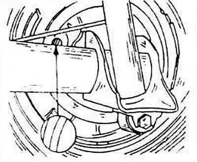
On the back side of the brake support plates there are plugs, after removing which you can check the thickness of the brake pads. The picture shows where the inspection hole is located. Illuminate it with a flashlight, if the pad is worn out and its thickness is approximately 265 mm, you need to replace the pads as a set, i.e. on both wheels.
Raise the rear of the car and place it on jack stands.
Secure the front wheels (bricks).
The adjuster for self-adjusting brakes must be disconnected, as the brake shoes may be hanging on the drum. To do this, insert a screwdriver through the threaded holes into the drum, find the installation wedge and slide it up. The adjuster sits on the upper left side of the drum.
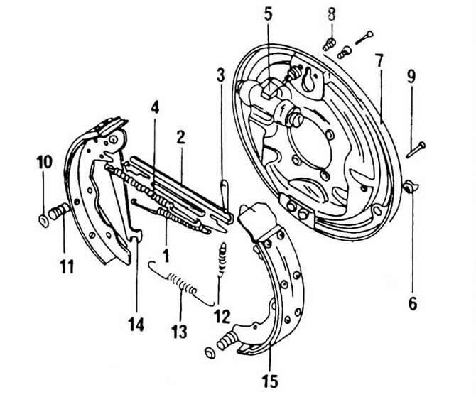
1 - Upper spring of brake pad return stroke
2 - a pressure piece placed between the pads
3 - installation wedge
4 - return spring
5 - wheel brake cylinder
6 - plug
7 - brake support plate
8 - Allen screw
9 - brake shoe anchor pin
10 - spring seat
11 - compression spring
12 - return adjustment spring
13 - lower spring of brake pad return stroke
14 - handbrake lever
15 - brake pads
Carefully pry off the hub cap using a screwdriver or special tool.
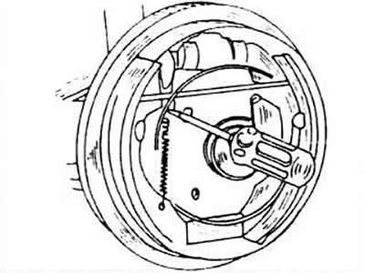
Remove the brake drum. If it should sit firmly, use a screwdriver to push the mounting wedge upwards again. The brake drum has been removed to demonstrate the operation more clearly.
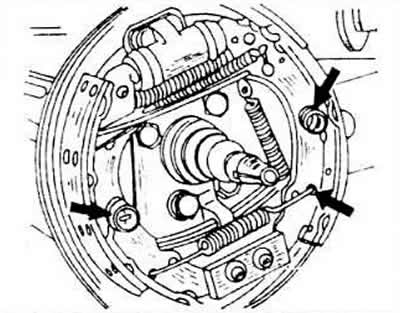
From the back side, press your finger on the anchor pins and use pliers to grasp the spring disc from the outside of the pad (top arrows), press inward and then turn until the head of the pin can be inserted through the spring disc. Remove the spring disc, spring and pin. Perform this operation on both pads.
Grasp the shoe from the bottom with your hand and lift it out of the support. Unhook the released return spring.
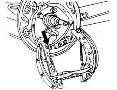
Tilt both brake shoes down and unhook the handbrake cable from the shoe.
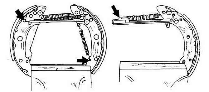
Clamp the brake shoes in a vice and use pliers to release the wedge return spring and the upper return spring. Remove both shoes as well as the pressure piece located at the top.
Clamp the brake shoes with the pressure piece between them in a vice and remove the pressure piece from the shoes until the spring is released and can be unhooked and removed completely. Remove the setting wedge as well, but pay attention to how it is inserted.
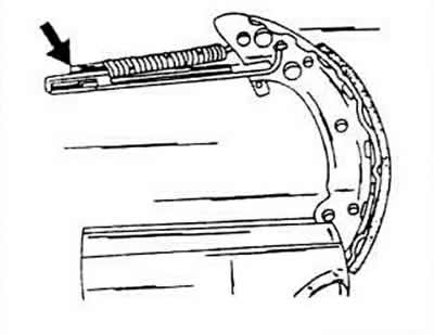
Clean all parts thoroughly. Pay particular attention to the condition of the rubber caps of the brake cylinders. If damp areas are found, repair or replace the cylinder.
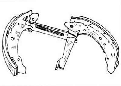
Clamp the pads in a vice, hang the spring and insert the pressure lever into the pads. Perform both manipulations simultaneously. To do this, stretch the spring until you can hook it.
Insert the installation wedge into the brake shoes (in accordance with the installation method shown earlier) and assemble both pads. Hang the upper return spring. To hang the spring accurately, refer to the brake assembly diagram.
Hang up the handbrake cable, push both brake shoes upwards and insert the upper ends of the shoes into the wheel brake cylinder pistons without damaging the rubber seals.
Hang the lower return spring and place the left shoe on the support.
Hang the return spring of the installation wedge (pliers) and use a screwdriver to lift the shoe above the support.
Install the anchor pins in the reverse order of removal.
Install the brake drum and adjust the wheel bearing clearance.
Apply the brakes several times to activate the additional adjustment mechanism.
Visitor comments