
- Always replace exhaust manifold gaskets.
- Always replace gaskets between manifold flange and muffler downpipe.
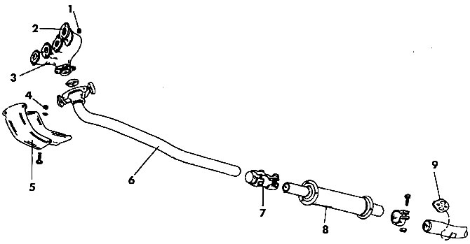
Pic. 264. The front of the exhaust system: 1 - nut (25 Nm); 2 - manifold gasket; 3 - exhaust manifold; 4 - nut (10 Nm); 5 - heat shield (turbodiesel); 6 - receiving pipe; 7 - connector; 8 - front muffler; 9 - rubber suspension
The exhaust manifold is replaced as follows:
- Wait for the system to cool down.
- Spacing between pins of special tool 3049A (pic. 265) align with the gaps between the holes in the spring plate. The direction of rotation to compress the plate is indicated by an arrow on the plate.
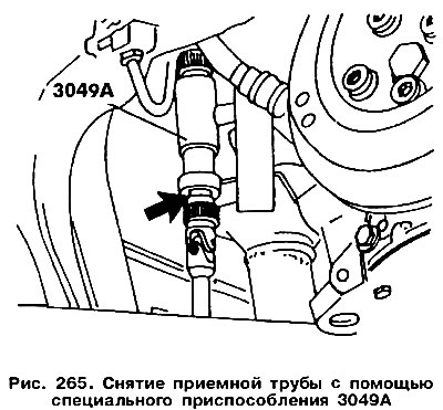
- Insert the pins of the tool into the holes in the spring plate. The adjustable side of the fixture must be pointing down, as shown in fig. 265. The arrow points to the place where the spring plate should be. Insert the tee into the fixture and feed the fixture until it stops.
- While moving the downpipe in the direction of the removed spring plate, remove the plate.
- Loosen the nuts and remove the exhaust manifold and its gaskets.
The exhaust manifold is installed in the reverse order, taking into account the following:
- Always replace the exhaust manifold gaskets and the gaskets between the manifold flange and downpipe.
- During installation, insert the spring plate into the cutout of the exhaust manifold and then compress tool 3049. The other end can then be secured.
- Check if the plate is seated correctly in the cutout.
- When installing the downpipe, secure the clamp loosely. Align all elements of the system and only then tighten the clamp nuts with a torque of 25 Nm.
- Tighten the nuts and bolts of all other elements, as well as the exhaust pipe mounting bolts, with a torque of 25 Nm.
- Replace the rubber hangers, paying attention to their design, as they are not all the same.
- When installing the rear muffler, check if the rubber-metal ring is damaged. Tighten the fixing nuts to a torque of 25 Nm.
- After finishing work, start the engine and check at idle to see if the elements of the exhaust system hit the elements of the body structure.
On fig. 266 shows the middle and rear parts of the exhaust system. Replacing these nodes is not particularly difficult. Tighten the nuts and bolts of all clamps with a torque of 25 Nm.
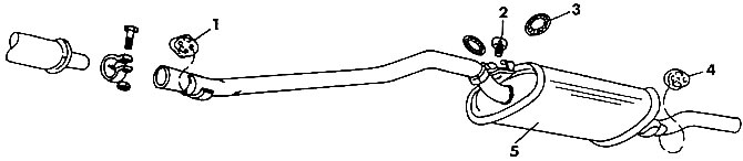
Pic. 266. The middle and rear parts of the exhaust system: 1 - rubber suspension; 2 - rubber limiter; 3 - ring; 4 - rubber suspension; 5 - rear muffler
Visitor comments