
English Русский
Български
Беларускі
Український
Српски
Hrvatski
Română
Polski
Slovenský
Magyar
  |  Articles  |  Sitemap  |  Contacts  |    |
Car maintenance Ford Car maintenance Hyundai Car maintenance Chevrolet Car maintenance BMW Car maintenance Audi Car maintenance Opel Car maintenance AvtoVAZ
VWmanual.ru


Main   Passat   Golf   Polo   Touareg   Tiguan   Sharan   Transporter   Others  
Golf 1 (1974-1984, diesel) Golf 1 (1974-1984, petrol) Golf 2 (1984-1993, petrol) Golf 2 (1984-1993) Golf 3 (1991-1997) Golf 4 (1997-2004) Golf 5 (2003-2008)

Ventilation and heating with air conditioning system (VW Golf 2)

  • Main
  • Golf
  • Golf 2
  • General information
  • User manual
  • Ventilation and heating with air conditioning system
            0


Contents: Air ducts/nozzles ↓ Governing bodies ↓ Removal ice from the windshield and…↓ Eliminating fogging of glass ↓ Accelerated heating of the passenger…↓ Air cooling ↓ Maximum air cooling ↓ Normal cooling mode ↓
In order to create comfortable driving conditions, some Volkswagen vehicles are equipped with an air conditioning system in combination with the heating, ventilation, anti-icing/anti-fog system. Since the air conditioner does not work properly at low ambient temperatures, it must be switched on when the outside temperature is above 2°C.

When the air conditioner is turned on, the temperature and humidity inside the car are monitored. If the outside air humidity is high, make the appropriate adjustments to avoid glass fogging. The maximum air cooling effect can be achieved with the windows closed. However, if the air temperature inside the car is too high (for example, the car was standing in the sun for a long time), open the windows for a few minutes to allow the hot air to escape from the car.

Air ducts/nozzles


Depending on the position of the temperature control lever, heated or unheated air will flow from outside through all open nozzles. All nozzles in the dashboard can also be opened or closed individually using the dial switches located next to each nozzle. To adjust the peripheral air flows, use the central lever located in each nozzle. To adjust the air flow in height, move the nozzle cover in the desired direction.

Governing bodies


Fan switch


If the system is not switched off, the fan will start to operate at a reduced speed as soon as the ignition is switched on. Adjust the intensity of the incoming air by selecting one of the three fan speeds by turning switch A (figure 23).
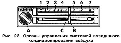


If the system is not switched off, the fan will start to operate at a reduced speed as soon as the…


Air temperature control lever


Select the required temperature value by moving lever B between two extreme positions: left (COOLER) and right (HEATER).

Heating and ventilation control lever


Below is information about the operation of the system in certain positions of lever C:

1 — "OFF" (switched off)
  • The system is not working.
  • The fan is off.
  • Outside air does not enter the system.

2 — Maximum cooling

The maximum cooling effect of the air coming through nozzles 3 and 4 in the instrument panel is achieved by setting the temperature control lever to the extreme left position.


3 — Conventional cooling

The air conditioner compressor is operational at an outside air temperature above 20 C. The outside air flow entering through nozzles 3 and 4 (see figure 22) in the instrument panel, cooled when the temperature control lever is set between the central and leftmost positions.

4 — Comfortable conditions

Depending on the position of the temperature control lever, the main air flow entering the cabin through nozzles 3 and 4 (see figure 22) and air channels 5 in the footwell, can be cooled, heated and unheated. Additional air flow can come through the nozzles of the windshield and side windows.

5 — Ventilation

The air conditioner compressor does not work. Heated or unheated air flow comes from outside through open nozzles 3 and 4 (see figure 22) in the dashboard.

6 — Heating

The air conditioner compressor does not work. The air flow is circulated through the air ducts 5 (see figure 22), located in the footwell. Additional air flow can be supplied via the windshield and side vents. Close the vents 3 in the instrument panel. Additional warm air flow from the open vents 4 in the instrument panel can also be directed to the side windows.

7 — Defrosting, fog dissipation, moisture absorption

Depending on the position of the temperature control lever, the main air flow circulating through nozzles 1, 2 (see figure 22), can be heated or unheated. Additional air flow can come through the air ducts 5 located in the footwell. Close the nozzles 3 and 4 in the instrument panel.

Removal ice from the windshield and side windows


Set both levers to the extreme right position.

Set the fan switch to the horizontal position .

Eliminating fogging of glass


Set the upper lever to the extreme right position. On rainy days or days with high humidity outside, the air conditioner is extremely useful for quickly absorbing moisture inside the cabin and eliminating fogging of the windshield and side windows.

On cool days with high humidity, move the lower lever to the right (HEATER).

On hot days with high humidity, move the lower lever to the left (COOLER).

Set the fan switch to position 3.

Accelerated heating of the passenger compartment


Move the upper lever to the position .

Move the lower lever to the extreme right position.

Set the fan switch to position 3.

Air cooling


Move the upper lever to the position .

Use the lower lever to select the desired temperature.

Set the desired fan operating mode.

Adjust the vents in the dashboard to create comfortable conditions for you and your passengers.

Maximum air cooling


Since there is no exchange with the outside environment, it is recommended to perform the following operations to quickly cool the air inside the cabin or use this function for a short time.

Close all windows.

Move the upper lever to position 2 (see figure 23).

Move the lower arm to the extreme left position or to another required position in the area between the left and center marks.

Set the fan switch to position 4.

Open or close all the vents in the instrument panel and adjust the air flow direction. Never close all four vents in the instrument panel, as this may cause ice to form in the evaporator.

Normal cooling mode


Move the upper lever to position 3 (see figure 23).

Use the lower lever to set the desired temperature.

The original article is available at: VWmanual.ru

Select the fan operating mode.

Open or close the nozzles in the instrument panel and adjust the direction of the air flow. When the upper lever is set to the position make sure that at least one nozzle in the instrument panel is open, this will prevent ice from forming in the evaporator.

This article is available at russian, bulgarian, belarusian, ukrainian, serbian, croatian, romanian, polish, slovak, hungarian
The text has been checked: Kolesnikov Artem

Share information:

Previous articles
Ventilation and heating
Windscreen and rear window wipers and washers (Golf)
Lighting and signaling
Steering wheel tilt adjustment
Gear shifting
Multifunctional display
Next articles
Gear and fuel consumption indicator
Doors and windows
Adjusting the front seats
Wheel replacement
Checking the level of working fluids
Replacing the air filter element


Similar articles from other manuals for VW cars:
Heating and ventilation system device Passat B5 (1996-2005)
Heating and ventilation system Polo 3 (1995-2003)
Electrical diagram of the Climatronic air conditioning system Touareg 1 (2002-2006)
Checking the drain hose for water condensate of the heating and… Tiguan 1 (2007-2015)
Checking the operation of the lighting system Sharan 1 (1995-2000)
Ignition system, Digifant control unit, electric crankcase… Transporter T3 (1979-1992)
Heating and ventilation system LT 2D (1996-2003)
Link to this page in different formats


Visitor comments


No comments yet


How much will 48 + 29 =


Golf 5 
  • General information
  • User manual
  • Maintenance
  • Troubleshooting
  • Power unit
  • Engine repair
  • Cooling and ventilation system
  • Fuel system
  • Ignition system
  • Transmission
  • Clutch
  • Mechanical gearbox
  • Automatic gearbox
  • Chassis
  • Brake system
  • Car suspension
  • Steering
  • Body
  • Interior (internal elements)
  • Exterior (external elements)
  • Doors and covers
  • Electrical equipment
  • Power devices
  • Washers and wipers
  • Lighting and appliances
  • Electrical circuits
Golf 4 
  • General information
  • User manual
  • Weekly checks
  • Maintenance
  • Power unit
  • Petrol engines
  • Diesel engines
  • Cooling system
  • Fuel system (petrol)
  • Control system (petrol)
  • Fuel system (diesel)
  • Exhaust system
  • Transmission
  • Clutch
  • Car gearbox
  • Drive shafts
  • Chassis
  • Car suspension
  • Steering
  • Wheels and tires
  • Brake system
  • Body
  • Exterior (external elements)
  • Interior (internal elements)
  • Ventilation and heating
  • Car doors and sunroof
  • Washers and glass cleaners
  • Electrical equipment
  • Power devices
  • Lighting and appliances
  • Electrical circuits
Golf 3 
  • Petrol engine
  • Engine repair
  • Lubrication system
  • Cooling system
  • Ignition system
  • Diesel engine
  • Engine repair
  • Diesel injection system
  • Pre-glow system
  • Transmission
  • Clutch
  • Gearbox and drive shafts
  • Chassis
  • Steering
  • Wheels and suspension
  • Brake system
  • Electrical equipment
  • Lighting and appliances
  • Electrical circuits
Golf 2 
  • General information
  • Introduction to guide
  • User manual
  • Petrol engines 1.3 l
  • Engine repair
  • Lubrication system
  • Cooling system
  • Carburetors
  • Supply system
  • Ignition system
  • Petrol engines 1.6/1.8 l
  • Engine repair
  • Supply system
  • Ignition system
  • Diesel engines
  • Engine repair
  • Lubrication system
  • Cooling system
  • Power and exhaust system
  • Transmission
  • Clutch
  • 4-speed gearbox 084
  • 5-speed gearbox 085
  • 4-speed gearbox 020/4R
  • 5-speed gearbox 020/4T
  • Automatic gearbox
  • Drive shafts
  • Chassis
  • Steering
  • Car suspension
  • Brake system
  • Body
  • Body elements
  • Doors, locks and windows
  • Electrical equipment
  • Equipment and devices
  • Power devices
Golf 2 (petrol) 
  • General information
  • Characteristics
  • Car care
  • Maintenance
  • Power unit
  • Engine repair
  • Engine 1.05/1.30
  • Engine 1.60/1.80
  • Cooling and lubrication system
  • Power and exhaust system
  • Transmission
  • Clutch
  • Car gearbox
  • Drive shafts
  • Chassis
  • Brake system
  • Steering
  • Suspension
  • Body
  • Body and equipment
  • Electrical equipment
  • Lighting and appliances
  • Electrical circuits
Golf 1 (petrol) 
  • General information
  • Characteristics
  • User manual
  • Maintenance
  • Power unit
  • Engine adjustment
  • Engine 1.1/1.3
  • Engine 1.5/1.6/1.8
  • Engine electrical equipment
  • Cooling system
  • Fuel system
  • Transmission
  • Clutch and manual gearbox
  • Automatic gearbox
  • Chassis
  • Steering
  • Front suspension
  • Rear suspension
  • Brake system
  • Electrical equipment
  • Lighting and appliances
  • Electrical circuits
  • Body
  • Body and equipment
  • Optional equipment
Golf 1 (diesel) 
  • General information
  • Specifications
  • Maintenance
  • Power unit
  • Engine repair
  • Exhaust and turbocharger
  • Cooling system
  • Fuel system
  • Fuel injection system
  • Transmission
  • Clutch and drive shafts
  • Car gearbox
  • Chassis
  • Suspension and wheels
  • Steering
  • Brake system
  • Wheels and tires
  • Body
  • Heating and ventilation
  • Exterior (external elements)
  • Interior (internal elements)
  • Doors and windows
  • Electrical equipment
  • Equipment and devices
  • Lighting system
  • Power devices
  • Electrical circuits
VWmanual.ru © 2016-2026 | Mobile version | News and articles | Sitemap: EN BG BY UA RS HR RO PL SK HU | Write message | Site search
Passat B2 • Passat B3 • Passat B4 • Passat B5 • Passat B6 • Golf 1, diesel • Golf 1, petrol • Golf 2, petrol • Golf 2 • Golf 3 • Golf 4 • Golf 5 • Polo 3 • Polo 4 • Touareg 1 • Tiguan 1 • Sharan 1 • Transporter T3 • Transporter T4 • LT 28 • LT 2D • Beetle • Caddy 3 •
Our website uses cookies to ensure functionality and convenience.