English Русский
Български
Беларускі
Український
Српски
Hrvatski
Română
Polski
Slovenský
Magyar
  |  Articles  |  Sitemap  |  Contacts  |    |
Car maintenance Ford Car maintenance Hyundai Car maintenance Chevrolet Car maintenance BMW Car maintenance Audi Car maintenance Opel Car maintenance AvtoVAZ
VWmanual.ru


Main   Passat   Golf   Polo   Touareg   Tiguan   Sharan   Transporter   Others  
Golf 1 (1974-1984, diesel) Golf 1 (1974-1984, petrol) Golf 2 (1984-1993, petrol) Golf 2 (1984-1993) Golf 3 (1991-1997) Golf 4 (1997-2004) Golf 5 (2003-2008)

Ventilation and heating (VW Golf 2)

  • Main
  • Golf
  • Golf 2
  • General information
  • User manual
  • Ventilation and heating
            0


Contents: Governing bodies ↓ Air ducts/nozzles ↓ Removal ice from windshield and side…↓ Elimination of fogging of windshield…↓ Accelerated heating of the passenger…↓ Maintaining comfortable conditions…↓ Ventilation ↓ General recommendations ↓
Important! Good visibility and overview for the driver is achieved provided that the windows are clear of condensation, ice and fogging. In order to ensure safe driving conditions, it is extremely important to carefully read and strictly follow the instructions and rules for using ventilation and heating set out below. If necessary, contact a Volkswagen dealer. Maximum heating intensity and rapid defrosting can be obtained when the engine has reached operating temperature.


But your car's fresh air system provides ventilation while driving. Air flows through the ventilation grille on the engine hood, enters the passenger compartment through the nozzles in the dashboard and footwell, and exits through the ventilation slots in the side decorative panel of the luggage compartment. When placing luggage or other objects, make sure that they do not block the ventilation slots.

Governing bodies


Heating and ventilation control lever


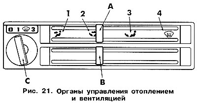
Select the air flow distribution you require by moving lever A (figure 21) to the corresponding symbol. The main air flow comes through the air ducts located in places with the corresponding symbol. To create more comfortable conditions, additional air flows can be created from other air ducts (except for the situation when the lever is set to the position ).

Select the air flow distribution you require by moving lever A (figure 21) to the corresponding…


Heating and ventilation control lever positions


See below for information on air flow and ventilation locations.


windshield nozzles 1 and 2 are open (figure 22).

air ducts 5 in the footwell are open (front and back).

nozzles 3 and 4 in the instrument panel are open, along with air ducts 5 in the footwell.

nozzles 3 and 4 in the instrument panel are open.
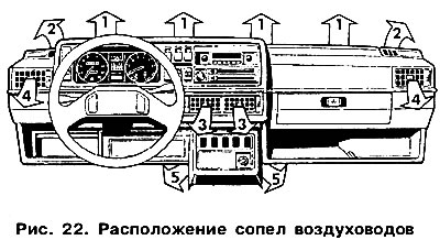
nozzles 3 and 4 in the instrument panel are open.


Air temperature control lever


Set the required temperature by moving lever B (see figure 21) between the extreme left and extreme right positions. Move the lever to the right to increase the temperature, to the left to decrease the temperature.


Fan switch


Adjust the air flow intensity by selecting the appropriate fan speed by turning its switch C (see figure 21).

Air ducts/nozzles


Depending on the position of the air temperature control lever, heated or unheated air will flow from outside through all open nozzles. Nozzles 3 and 4 (see figure 22) the instrument panel can also be opened or closed individually using the rotary switches located next to each nozzle.

Disc switch at the top - nozzle open.

Disc switch at the bottom - nozzle closed.

To adjust the air flow at the edges, use the central lever located in each nozzle.

To adjust the air flow height, move the nozzle guide in the required direction.

Removal ice from windshield and side windows


Move both levers to the extreme right position. Turn the fan switch to the horizontal position.

Elimination of fogging of windshield and side windows


When the air humidity is high or on rainy days, the windshields and side windows fog up. In this case, do the following to eliminate fogging:
  • Set the upper lever to the position between the symbols and (see figure 21).
  • Set the fan switch to the symbol or to position 3. It would be very useful to set the air temperature control lever approximately in the middle of the section between its central and the right-hand position.
  • Close nozzles 3 (see figure 22) on the dashboard.
  • The additional flow of warm air coming out of the nozzles 4 in the instrument panel can also be directed to the side windows.

Accelerated heating of the passenger compartment


Move the upper lever to the far left position.

Move the lower lever to the extreme right position.

Open nozzles 3 and 4 in the instrument panel.

Turn the fan switch to the horizontal position.

Maintaining comfortable conditions inside the cabin


After cleaning all the glass and heating the interior, set the regulators as follows:
  • Place the upper lever between the symbols and (see figure 21).
  • Use the lower lever to set the desired temperature.
  • Set the fan switch to position 1 or 2.
  • Close nozzles 3 (see figure 22) on the dashboard.
  • Adjust the direction of the warm air flow coming through the nozzles 4 in the instrument panel.

Ventilation


To ensure maximum air circulation inside the cabin, move both levers to the extreme left position and set the desired fan mode.

General recommendations


To maintain air circulation, it is recommended to keep the fan running at low speeds.

To ensure unimpeded air flow and to create effective ventilation and heating conditions, regularly clear the air intake vents in front of the windshield of ice, snow, and leaves.

The article is posted on the portal: VWManual

To prevent exhaust gases and polluted air from entering the passenger compartment, close the windows, the air vents in the instrument panel and set the upper lever to the extreme left position.

On vehicles equipped with an air filter, such actions are necessary if the outside air is polluted.

Dust is captured by the filter.

Both control levers can be set to any intermediate position.

The fan switch has no intermediate positions.

This article is available at russian, bulgarian, belarusian, ukrainian, serbian, croatian, romanian, polish, slovak, hungarian
The text has been checked: Kolesnikov Artem

Share information:

Previous articles
Windscreen and rear window wipers and washers (Golf)
Lighting and signaling
Steering wheel tilt adjustment
Gear shifting
Multifunctional display
Starting a car engine
Next articles
Ventilation and heating with air conditioning system
Gear and fuel consumption indicator
Doors and windows
Adjusting the front seats
Wheel replacement
Checking the level of working fluids


Similar articles from other manuals for VW cars:
Heating and ventilation (manual heater) Passat B3 (1988-1993)
Heating and ventilation system Polo 3 (1995-2003)
Laying the ventilation tube on the transfer case Touareg 1 (2002-2006)
Checking the heating element of the additional air heater Tiguan 1 (2007-2015)
Fans for cooling systems (150, 250W), heating and ventilation Transporter T4 (1990-2003)
Heating and ventilation system LT 2D (1996-2003)
Link to this page in different formats


Visitor comments


No comments yet


How much will 11 + 37 =


Golf 5 
  • General information
  • User manual
  • Maintenance
  • Troubleshooting
  • Power unit
  • Engine repair
  • Cooling and ventilation system
  • Fuel system
  • Ignition system
  • Transmission
  • Clutch
  • Mechanical gearbox
  • Automatic gearbox
  • Chassis
  • Brake system
  • Car suspension
  • Steering
  • Body
  • Interior (internal elements)
  • Exterior (external elements)
  • Doors and covers
  • Electrical equipment
  • Power devices
  • Washers and wipers
  • Lighting and appliances
  • Electrical circuits
Golf 4 
  • General information
  • User manual
  • Weekly checks
  • Maintenance
  • Power unit
  • Petrol engines
  • Diesel engines
  • Cooling system
  • Fuel system (petrol)
  • Control system (petrol)
  • Fuel system (diesel)
  • Exhaust system
  • Transmission
  • Clutch
  • Car gearbox
  • Drive shafts
  • Chassis
  • Car suspension
  • Steering
  • Wheels and tires
  • Brake system
  • Body
  • Exterior (external elements)
  • Interior (internal elements)
  • Ventilation and heating
  • Car doors and sunroof
  • Washers and glass cleaners
  • Electrical equipment
  • Power devices
  • Lighting and appliances
  • Electrical circuits
Golf 3 
  • Petrol engine
  • Engine repair
  • Lubrication system
  • Cooling system
  • Ignition system
  • Diesel engine
  • Engine repair
  • Diesel injection system
  • Pre-glow system
  • Transmission
  • Clutch
  • Gearbox and drive shafts
  • Chassis
  • Steering
  • Wheels and suspension
  • Brake system
  • Electrical equipment
  • Lighting and appliances
  • Electrical circuits
Golf 2 
  • General information
  • Introduction to guide
  • User manual
  • Petrol engines 1.3 l
  • Engine repair
  • Lubrication system
  • Cooling system
  • Carburetors
  • Supply system
  • Ignition system
  • Petrol engines 1.6/1.8 l
  • Engine repair
  • Supply system
  • Ignition system
  • Diesel engines
  • Engine repair
  • Lubrication system
  • Cooling system
  • Power and exhaust system
  • Transmission
  • Clutch
  • 4-speed gearbox 084
  • 5-speed gearbox 085
  • 4-speed gearbox 020/4R
  • 5-speed gearbox 020/4T
  • Automatic gearbox
  • Drive shafts
  • Chassis
  • Steering
  • Car suspension
  • Brake system
  • Body
  • Body elements
  • Doors, locks and windows
  • Electrical equipment
  • Equipment and devices
  • Power devices
Golf 2 (petrol) 
  • General information
  • Characteristics
  • Car care
  • Maintenance
  • Power unit
  • Engine repair
  • Engine 1.05/1.30
  • Engine 1.60/1.80
  • Cooling and lubrication system
  • Power and exhaust system
  • Transmission
  • Clutch
  • Car gearbox
  • Drive shafts
  • Chassis
  • Brake system
  • Steering
  • Suspension
  • Body
  • Body and equipment
  • Electrical equipment
  • Lighting and appliances
  • Electrical circuits
Golf 1 (petrol) 
  • General information
  • Characteristics
  • User manual
  • Maintenance
  • Power unit
  • Engine adjustment
  • Engine 1.1/1.3
  • Engine 1.5/1.6/1.8
  • Engine electrical equipment
  • Cooling system
  • Fuel system
  • Transmission
  • Clutch and manual gearbox
  • Automatic gearbox
  • Chassis
  • Steering
  • Front suspension
  • Rear suspension
  • Brake system
  • Electrical equipment
  • Lighting and appliances
  • Electrical circuits
  • Body
  • Body and equipment
  • Optional equipment
Golf 1 (diesel) 
  • General information
  • Specifications
  • Maintenance
  • Power unit
  • Engine repair
  • Exhaust and turbocharger
  • Cooling system
  • Fuel system
  • Fuel injection system
  • Transmission
  • Clutch and drive shafts
  • Car gearbox
  • Chassis
  • Suspension and wheels
  • Steering
  • Brake system
  • Wheels and tires
  • Body
  • Heating and ventilation
  • Exterior (external elements)
  • Interior (internal elements)
  • Doors and windows
  • Electrical equipment
  • Equipment and devices
  • Lighting system
  • Power devices
  • Electrical circuits
VWmanual.ru © 2016-2026 | Mobile version | News and articles | Sitemap: EN BG BY UA RS HR RO PL SK HU | Write message | Site search
Passat B2 • Passat B3 • Passat B4 • Passat B5 • Passat B6 • Golf 1, diesel • Golf 1, petrol • Golf 2, petrol • Golf 2 • Golf 3 • Golf 4 • Golf 5 • Polo 3 • Polo 4 • Touareg 1 • Tiguan 1 • Sharan 1 • Transporter T3 • Transporter T4 • LT 28 • LT 2D • Beetle • Caddy 3 •
Our website uses cookies to ensure functionality and convenience.