



Contents: Removal ↓ Installation ↓ Installation of high pressure lines ↓ Installation of separate injection…↓ Installing the fuel line (between…↓
Removal
Remove the engine casing. Remove the sound insulation from the cylinder head cover. Disconnect connectors "1" from the injectors being removed.
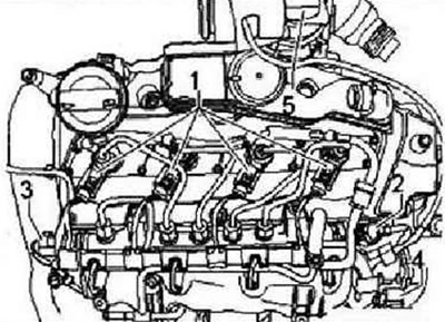
Disconnect the fuel return line fittings from the removed injectors. To do this, press the fitting down by the protrusions and pull the middle part upward to unlock it.
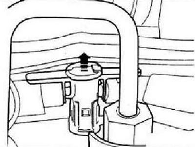
Instructions: It is necessary to ensure that the area is kept clean and that no dirt gets into the removed return fuel lines and injector connectors.
Remove the high-pressure pipe between the rail and the injector to be removed. Unscrew the screws securing the cover of the injector to be removed. Raise the cover slightly, then turn it 90° to gain access to the injector mounting nuts.
Caution: If the injector mounting nuts are unscrewed or screwed in carelessly, there is a high probability that they will fall inside the cylinder head. Therefore, this operation should be carried out with maximum care in order to avoid unplanned installation work and subsequent engine damage.
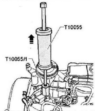
Loosen the fastening nuts of the corresponding injector. Install the inertial puller "T10055" with the adapter -T10055/1- as shown in the figure, and remove the injector from the socket with light blows.
Installation
Important instructions to follow when installing injectors.
The following components and gaskets or O-rings must be replaced each time they are removed and installed: "pressure plate", "copper washer", "injector seat sealing ring", "injector return sealing ring". When installing a new injector, the following parts and seals or O-rings must be replaced: "pressure plate", "injector line", "copper washer", "injector well sealing ring", "injector return sealing ring". When reinstalling the injector, install it only in its original place (cylinder). Before installation, check the cleanliness of the injectors and their seats. The injectors must not have any damage. Before installation, lubricate all O-rings with assembly or engine oil.
Procedure for installing a used one (used furniture) injectors
Apply corrosion remover to the nozzle tip (from an aerosol can). After five minutes, remove any soot and oil particles with a rag. To remove the old copper injector sealing ring, carefully clamp it in a vice so that the injector itself can be rotated between the jaws of the vice. Remove the injector from the copper sealing ring with light rotational and translational movements. Install a new copper sealing ring using a plastic bushing. To avoid damaging the new rubber sealing ring "2" of the fuel return line connector, install it by sliding it along the mounting rod "1". To remove soot particles from the mounting surface, clean the injector well in the cylinder head with a rag soaked in motor oil or a corrosion remover. Do not damage the mounting surface.
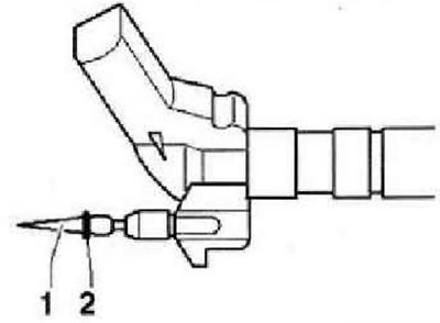
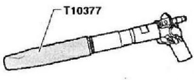
Replace the injector well sealing ring using the T10377 mandrel. Install the injector cover. Install the pressure plate on the injector in the proper mounting position. Insert the injector into the cylinder head well.
(View the original on this resource: www.VWManual.ru)
Caution: If the injector mounting nuts are unscrewed or screwed in carelessly, there is a high probability that they will fall inside the cylinder head. Therefore, this operation should be carried out with maximum care in order to avoid unplanned installation work and subsequent engine damage.
Carefully screw the clamp plate mounting nuts by hand and then tighten them. Turn the nozzle cover to the installation position and secure it with screws. Install the high-pressure lines.
Instructions: When replacing one or more injectors, it is necessary to write the "quantity correction value (IMA)" and "voltage correction value (ISA)" for the new injectors into the engine control unit.
Installation of high pressure lines
Caution: For the best and stress-free installation of the injection lines, loosen the fuel rail and slightly dare. Do not bend or stretch the lines under any circumstances. This would lead to a break in the corresponding line over time.
Instructions: Below is a description of how to install new injection lines. When reinstalling previously used injection lines, they must be checked according to the points given. The procedure is identical in both cases.
Installation of separate injection lines (cylinder between fuel rail and injector)
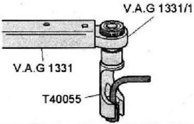
Remove the packaging of the new injection line, remove the plugs and install the line immediately between the fuel rail and the injector. First tighten the union nuts of the injection pipes by hand without a tool. Make sure that the line is correctly positioned in its place. If necessary, perform similar actions with the other injection lines. Tighten the fuel rail again if necessary. Tighten the union nuts of all newly installed injection lines using a torque wrench -VAG 1331- and a "T40055" attachment.
Installing the fuel line (between the injection pump and the fuel rail) or the entire set of highways
If not already done, disconnect the fuel rail mounting bolts and check them for wear. Then remove the packaging from the fuel line between the high-pressure fuel pump and the fuel rail, remove the plugs and immediately install the line. First, tighten the union nuts of the injection pipes by hand without a tool. Make sure that the line is correctly positioned in its place. If the entire kit is being installed, perform similar actions with the four injection lines. Mount all three mounting clamps above the fuel line, ensure alignment. Screw in the clamp mounting bolts by approximately 3 turns. Tighten the fuel rail again. Tighten the upper mounting clamp on the intake manifold to a torque of 8 Nm.
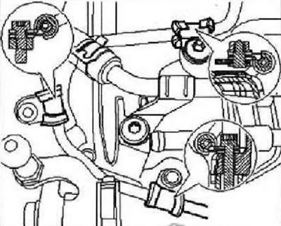
Tighten the union nuts of all newly installed injection lines using a torque wrench -VAG 1331- and a "T40055" attachment. Tighten the remaining two clamps to 8 Nm. Carefully place the unions of the return fuel lines on the injector sealing rings (check them for damage first). The fitting should lock with a clearly audible click. After this, it is necessary to carefully press the clamps down. Fill the system with fuel.
Visitor comments