
Safety regulations
ATTENTION: When carrying out installation work, especially in the engine compartment due to its dense layout, the following regulations must be observed. Highways of all types (e.g. fuel, hydraulic, activated carbon absorber, cooling system, air conditioning circuit, brake system, vacuum), as well as electrical wires must be laid as they were originally laid. Sufficient space must be provided when working on all moving or hot parts.
Removing
Caution: If there are mechanical defects in the turbocharger, for example, the destruction of the impeller of the pump section, it is not enough just to replace the turbocharger. In order to avoid subsequent damage, after carrying out repair work is necessary. Check the air filter housing, filter element and air intake hoses for contamination. Check for foreign bodies in the intake tract and intercooler. If found, remove them from the intake tract, if necessary, replace the intercooler.
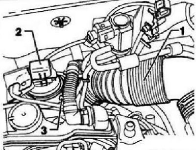
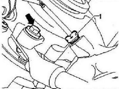
Detach air intake line -1- and disconnect connector from turbocharger guide vane position sender -G581- -2- at turbocharger. Detach vacuum line -3- from turbocharger.
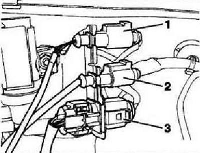
Unplug connector for exhaust gas temperature sensor 1-G235- -1- at front wall of plenum box and remove cable from brackets.
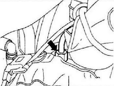
Unscrew oil supply line -arrow- from turbocharger.
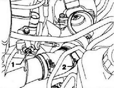
Unscrew fastening screw -1- for charge air pipe, loosen clamp -2- and disconnect connecting hose from turbocharger, pulling hose as far as possible. Remove particulate filter.
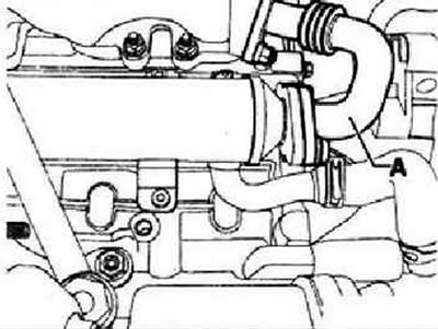
Remove connecting pipe -A- to exhaust gas recirculation cooler.
Caution: The exhaust gas temperature sender 1 -G235- blocks access to the upper turbocharger support bracket bolt. The sensor must not be bent, so it must be removed.
Remove exhaust gas temperature sensor 1 -G235-. Disconnect the right drive shaft from the transfer case. Unscrew the hollow screw of the turbocharger support bracket.
Unscrew upper bolt -arrow- for turbocharger support bracket.
Rotate the lower part of the support bracket by 90°and pull it downwards from the upper part. Remove the exhaust manifold heat shield. Loosen the exhaust manifold nuts. Remove the turbocharger by turning it with the air intake side down and then lowering it.
Installation
Caution: Before installation, check that the oil return bellows are not bent or kinked. If this is the case, then microcracks are likely to occur, which can lead to leaks. If necessary, replace the oil return line before installing the turbocharger.
Installation in reverse order. In doing so, observe the following. Install the turbocharger with the compressed air side up. Install the connection hose for the charge air connection before screwing on the turbocharger. Observe installation position of exhaust gas temperature sender 1 -G235-. Replace the banjo screw of the turbocharger support bracket and the O-rings of the oil return pipe. When installing the turbocharger support bracket, do not twist the oil return pipe bellows.
Visitor comments