



Contents: Removal ↓ Installation ↓
Attention: When disconnecting and connecting the battery, be sure to follow the sequence of actions described in the repair manual.
Removal
Disconnect the battery.
Remove the engine cover by pulling it up.
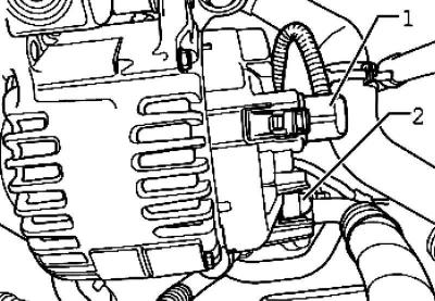
Fig. 7.12. Plug connection and protective cap
Disconnect the plug connection of the DF wire 1 and remove the protective cap 2 (Fig. 7.12).
Unscrew the B+ wire from the generator.
Caution: Before removing, mark the direction of travel and the top side of the poly V-belt with chalk or a marker. When installing, observe the correct direction of travel and the position of the sides of the belt.
Caution: Changing the direction of movement or sides of a previously used poly V-belt will damage it
Mark the direction of rotation of the poly V-belt.
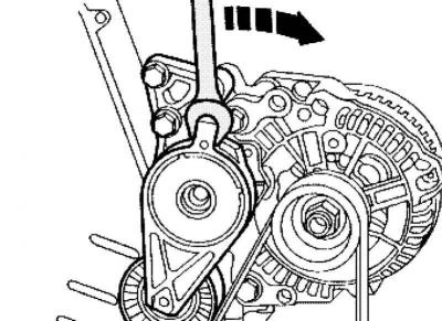
Fig. 7.13. Loosening the tension of the poly V-belt
Loosen the tension of the poly V-belt by turning the tensioner in the direction of the arrow (Fig. 7.13).
Secure the tensioner with the locking pin
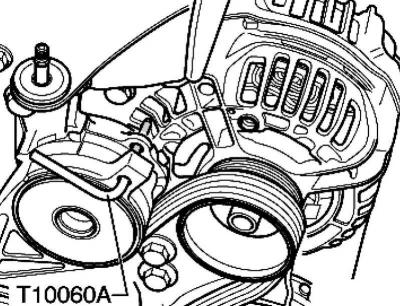
Fig. 7.14. Fixing the tension element
Remove the poly V-belt (Fig. 7.14).
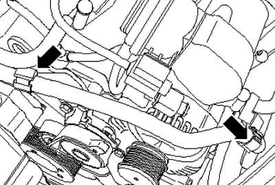
Fig. 7.15. Cooling system hose
Unlock the cooling system hose from the holder 1 and unscrew the fastening nut 2 (Fig. 7.15).
Remove the mounting bolts
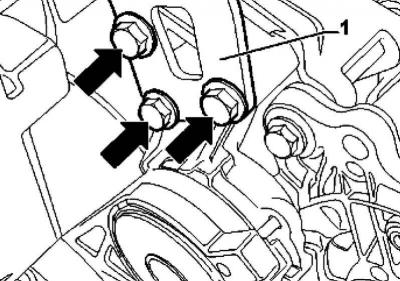
Fig. 7.16. Holder mounting bolts
Remove the holder together with the tension element from the vehicle (Fig. 7.16).
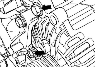
Fig. 7.17. Generator mounting bolts
Unscrew the generator mounting bolts (Fig. 7.17).
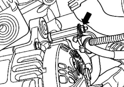
Fig. 7.18. Wire holder
Unscrew the wire holder from the generator (Fig. 7.18).
Remove the generator.
Installation
Installation is carried out in the reverse order, taking into account the following.
Caution: When installing a previously used poly V-belt, observe the direction of movement marked during removal
Before installing the poly V-belt, check that all units are securely fastened (generator, air conditioning compressor).
When routing the belt, ensure that the poly V-belt is positioned correctly on the pulleys
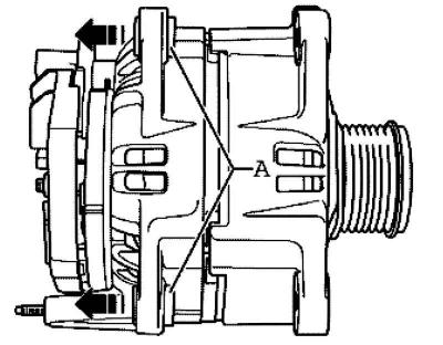
Fig. 7.19. Removing threaded bushings
Carefully knock out the threaded bushings A approximately 4 mm to the side, in the direction of the arrow, from the generator housing (Fig. 7.19).
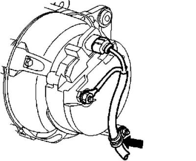
Fig. 7.20. Holder position
Screw the wire holder onto the back of the generator at the 3 o'clock position (clock face) (Fig. 7.20).
Tighten the connections to the specified torques.
Caution: Follow the instructions for attaching the terminals to the battery terminals.
Connect the battery.
Start the engine and check the belt operation.
Turn off the engine.
Visitor comments