



Contents: Checking the battery charge level ↓ Charging the battery ↓ Charging a completely discharged…↓ Battery Care ↓ Storage of the battery ↓ Self-discharge of the battery ↓ Removal and installation the battery ↓
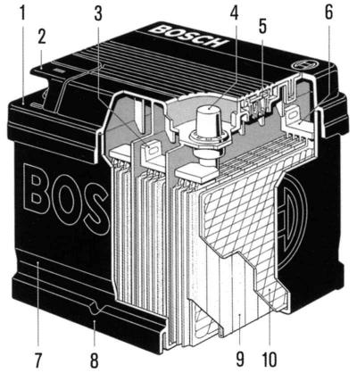
Fig. 7.5. Modern maintenance-free battery: 1 – housing cover; 2 – protective cover of terminals; 3 – inter-element connection; 4 – end terminal; 5 – element plugs (below under the lid); 6 – plate holder; 7 – body; 8 – Bottom reinforcement; 9 – positive plate, closed by a separator; 10 – negative plate
The vehicle covered in this manual has a 12-volt electrical system. The body ground is connected to the negative terminal of the battery. The battery is located in the engine compartment or under the rear seat (models with air conditioning, as well as some diesel modifications).
The battery performs three main functions in the vehicle's electrical system:
- provides electric current to start the engine;
- stabilizes the voltage in the electrical system,
- can provide current for a short time when the power consumption exceeds the generator output power.
Sealed battery packs are standard for all vehicles. They have no filler plugs on the hull. The battery pack is completely sealed, apart from two small side vents for ventilation. These vents allow the resulting gases to escape.
Sealed batteries have the following advantages over conventional batteries:
- to ensure longevity of batteries, there is no need to add water;
- the battery is protected from overcharging. If too much voltage is applied to the battery, it will not accept as much current as a regular battery. The increase in voltage will continue to charge the regular battery, which will cause gassing and loss of electrolyte;
- the battery is self-charging like a normal battery. This is very important when the car is parked in one place for a long time;
- with smaller dimensions and weight, the voltage and current remained the same.
The battery has two indicators:
- the capacity of the battery is determined at 27°C, which when fully charged provides 10.5 V or more;
- the cold start rating of a battery is determined by testing at -18°C, which shows the power of the battery when cranking the crankshaft with a cold engine.
The battery reserve capacity is defined as the maximum possible continuous time for driving at night with a minimum electrical load without using the generator output. Expressed in minutes, the reserve capacity (or the E indicator) is the time required for a fully charged battery at 27°C and discharged at 25 A to reach a terminal voltage of 10.5 V.
The cold cranking current test is performed at -18°C. This is the minimum current that the battery must be able to maintain at a given temperature while maintaining a minimum voltage of 7.2V.
This indicator is measured when starting a cold engine.
The service life of a battery is not unlimited. However, with proper care, the battery will last for many years.
If the battery tests well but exhibits performance issues for no apparent reason, the following factors may be the cause of the malfunction or failure:
- some appliance was left on all night;
- the car was moving at low speed for short periods;
- the vehicle's electrical load exceeded the generator's output, often with non-standard equipment being turned on;
- fault in the charging system: alternator belt slipping, alternator fault or voltage regulator fault, etc;
- improper use of the battery: failure to clean, clamps not tightened or clamps loosened;
- mechanical faults in the electrical system: shorted or pinched wires.
Sealed batteries have a built-in temperature compensated hydrometer in the top of the battery, which is used for the following diagnostics:
- When looking at the hydrometer, make sure the top of the battery is clean;
– during normal operation two readings should be obtained:
- Visible green dot - the appearance of green color, called "green dot" means the battery is ready for testing;
- Dark green invisible dot - if there are complaints about cold starting, the battery needs to be tested. At the same time, the electrical systems and charging should be checked. Sometimes a third condition may occur:
- Clear or light yellow - the fluid level is below the tip of the hydrometer. This may be due to overcharging or prolonged charging, excessive or normal battery wear. Therefore, the charging and electrical systems may need to be checked if there are complaints about cold starting. If the battery is the cause of the complaint about poor cold starting, replace it.
Checking the battery charge level
The density of the electrolyte together with the measurement of the voltage at the terminals of the battery allow you to make an accurate conclusion about the degree of charge of the battery. A hydrometer is used for checking, which can be purchased in a specialized store. The higher the density of the electrolyte, the more the float of the hydrometer rises (floats up). On the hydrometer scale, the values are expressed in units of density (g/cm³).
When measuring the density of the electrolyte, make sure that drops of electrolyte containing sulfuric acid, which causes corrosion and current leakage, do not fall from the hydrometer pipette onto the surface of the battery, the body and other parts.
When measuring the density of the electrolyte, the temperature of the electrolyte should be within 20-30?C. The density of the electrolyte should be measured in each element (can) of the battery. After measuring the density of the electrolyte, you can determine the degree of discharge of the battery.
In all elements the electrolyte must have the same density.
The density of the electrolyte in a fully charged battery is 1.28 g/cm³.
The density of the electrolyte in a battery discharged by 25% is 1.24 g/cm³.
The density of the electrolyte in a battery discharged to 50% is 1.20 g/cm³.
If the battery is discharged more than 25% in winter and more than 50% in summer, remove it from the vehicle and recharge it.
When measuring the electrolyte density, the electrolyte temperature should be within 20–30°C. The electrolyte density should be measured in each element (can) of the battery. After measuring the electrolyte density, the battery discharge level can be determined.
In all elements the electrolyte must have the same density.
The density of the electrolyte in a fully charged battery is 1.28 g/cm³.
The density of the electrolyte in a battery discharged by 25% is 1.24 g/cm³.
The density of the electrolyte in a battery discharged to 50% is 1.20 g/cm³.
If the battery is discharged more than 25% in winter and more than 50% in summer, remove it from the vehicle and recharge it.
Charging the battery
A battery with a green dot indicates that charging is not required until the battery is discharged, such as when starting a cold engine.
When charging a battery with sealed terminals outside the vehicle, install an adapter. Make sure all charger connections are clean and secure. For best results, the battery should be charged when the electrolyte and plates are at room temperature. Extremely cold batteries may not charge for several hours after charging begins.
Charge the battery until the green dot appears. During the charging process, the battery should be checked every 30 minutes. Tilt or shake may be necessary to make the green dot appear.
After charging, the battery should be tested.
The time required to charge the battery depends on:
- battery size - for a fully discharged high-capacity battery designed for heavy duty operation, the time required is 2 times longer than for charging the battery of a passenger car;
- temperature - it will take longer to charge a battery at -18°C than at 27°C. When the charger is connected to a cold battery, the charge level will be very low at first, but as the battery temperature rises, the charge level will increase;
- charger capabilities - a charger with a 5A charging current will take longer to charge than a charger with a 30A or higher charging current;
- state of charge - it takes twice as much charge to charge a completely discharged battery as it does to charge two half-discharged batteries, because in a completely discharged battery the electrolyte is almost pure water in composition and is a poor conductor. Then, as the charging current increases the acid content of the electrolyte, the state of charge increases accordingly.
Before charging, disconnect the positive and ground cables from the battery, the ground cable first.
Before charging, check the electrolyte level and add distilled water if necessary.
Frozen battery (a battery in which the electrolyte has frozen) defrost before charging. A fully charged battery freezes at -65°C, a half charged battery at -30°C, and a discharged battery at -12°C.
Charge the battery only in a well-ventilated area. When charging the installed battery, leave the hood of the car open.
During normal charging, the charging current value is approximately 10% of the battery capacity. (that is, a battery with a capacity of 50 A. h should be charged with a current of approximately 5.0 A). The charging time can be taken as 10 hours.
Connect the positive terminal of the battery to the positive wire, and the negative terminal of the battery to the negative wire of the charger.
During charging, the electrolyte temperature should not exceed +55°C; if necessary, interrupt charging or reduce the charging current.
Charge the battery until all battery cells begin to release gas abundantly and, with 3 measurements taken one hour after another, the electrolyte density and voltage stop increasing.
After charging, check the electrolyte level and add distilled water if necessary.
Charging a completely discharged battery
Use the following procedure to recharge a completely discharged battery:
- measure the voltage at the battery terminals with an accurate voltmeter. If the measured value is below 10 V, the charging current will be very low and it may take some time before the battery accepts an excess of a few milliamps;
- place the charger on a high place. Some chargers have a reverse polarity protection circuit that prevents charging if the battery terminals are connected incorrectly. A completely discharged battery does not have enough voltage to activate this circuit, even if the wires are connected correctly. This will result in the battery not charging. Therefore, follow the special instructions from the charger manufacturer to ensure that the charger turns on and starts charging a battery with low voltage;
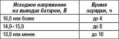
- the chargers have voltage and current regulators. The time required to charge the battery depending on different voltage values is given below.
Battery charging time depending on the initial battery voltage
If the charge received by the battery cannot be measured after the charging time has elapsed, the battery should be replaced.
If the charge received is measured during the charging process, the battery is OK and charging should be completed as usual.
If the charge received by the battery is not measured after the charging time calculated by the above method, the battery must be replaced.
If the charge received is measured during the charging time, the battery is good and charging should be completed in the normal manner.
Battery Care
The following tasks should be performed from time to time to ensure that the battery lasts longer and maintains its maximum capacity.
Always keep the battery and its surrounding parts clean. The surface of the battery must always be dry, otherwise, surface leakage currents may occur between individual cells, causing the battery to discharge itself.
The electrolyte level should always be at the ring located on the bottom of the filling chamber. Distilled water should be used for topping up.
In cold weather, do not leave the battery uncharged, as it (more precisely, the electrolyte in it) freeze. Weakly charged batteries freeze already at a temperature of about -10°C.
Storage of the battery
Batteries that are not used for a long time discharge themselves and may be subject to sulfation of the plates. If such batteries are charged with a fast charger, they do not accept the charging current due to the so-called surface charging.
Before rejecting a battery, you should check it:
- Check the density of the electrolyte. If the density in all elements differs by no more than 0.02 g/cm³, the battery should be charged with a charger.
- Check the battery after charging under load. If the values are not as required, the battery is faulty.
- Check the density of the electrolyte. If the density of the electrolyte in one or more cans is significantly lower than in the others (for example, in five cans the density is 1.16 g/cm³, and in one 1.08 g/cm³), the battery has an internal short circuit.
To avoid premature aging of the battery, the battery in storage should be charged every 3 months.
Self-discharge of the battery
Depending on the vehicle modification, the normal self-discharge of the battery is supplemented by the energy consumption of constantly operating energy consumers. Therefore, the battery in a non-operating vehicle should be charged once every six weeks. If there is a suspicion of surface leakage currents, the vehicle's on-board network should be checked.
Use a fully charged battery for testing.
Set the ammeter (with a measurement limit of 0-5 mA and 0-5 A) to the highest measurement limit. Connect the ammeter between the negative terminal of the battery and the ground cable. Connect the positive wire of the ammeter to the positive terminal of the battery, and the negative wire of the ammeter to the negative terminal of the battery.
Turn off all electrical consumers, close all doors and the trunk, turn off the engine compartment light.
Switch the ammeter measurement limit downwards until any readings appear (the acceptable value is 1–3 mA). Remove fuses from the fuse box one by one and open all electrical circuits in sequence. If the readings drop to 0 when one of the circuits is opened, the source of the fault should be sought in that circuit. Possible faults: corroded or dirty contacts of electrical connectors, frayed wires, internal short circuits in electrical equipment components.
If no fault is detected in the circuits protected by fuses, the wires should be disconnected from devices not protected by fuses: generator, starter, ignition system components.
If the ammeter reading drops to 0 when one of the unprotected circuits is disconnected, repair or replace the component in question. If there is a current leak in the starter or ignition system, always check (according to the diagram) ignition and starter switch.
Removal and installation the battery
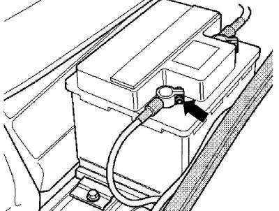
Fig. 7.6. Tightening the battery terminal fastening nut
When the battery is disconnected, the memory of the central control unit of the engine and gearbox, the anti-lock braking system, and a number of other electrical devices, such as the radio and clock, are erased of any faults that have occurred. After reconnecting, reprogram the relevant devices. Some serially installed radios have a security code. The security code prevents unauthorized use of the radio if its power supply has been disconnected. The power supply to the radio and clock is disconnected if, for example, the battery is disconnected, the radio is removed, or the corresponding fuse blows.
Remove the nuts and disconnect the negative terminal and then the positive terminal from the battery.
Loosen the battery support bracket mounting nut.
Remove the battery support bracket.
Remove the battery.
Before installation, clean the battery terminals; a brass wire brush will do the trick. Coat the battery terminals with a special grease to prevent corrosion.
Install the battery in the reverse order of removal.
Tighten the battery support bracket mounting nut to 6–8 N·m.
Tighten the battery terminal nuts to 9–12 N·m.
Visitor comments