
Location of electrical connectors on the back of the instrument cluster
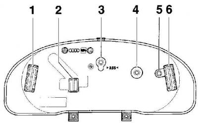
- 1 - 34-pin green electrical connector,
- 2 - 20-pin red electrical connector (installed only on the 3rd version),
- 3 - high beam control lamp 1.12 W,
- 4 - exhaust gas control lamp 1.12 W,
- 5 - control lamp of the trailer turns 1.12 W,
- 6 - 32-pin blue electrical connector
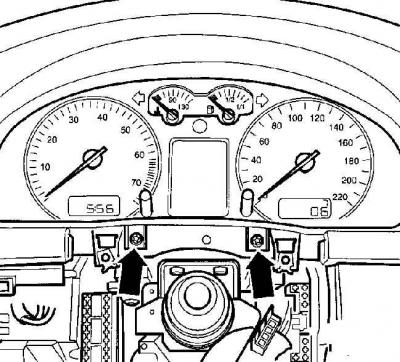
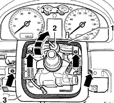
Location of instrument cluster mounting screws
Removing
Removing the lower side trim on the driver's side
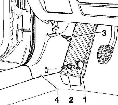
- 1 - plug,
- 2 - screw,
- 3 - screw,
- 4 - side trim
Removing the lower trim panel of the instrument panel on the driver's side
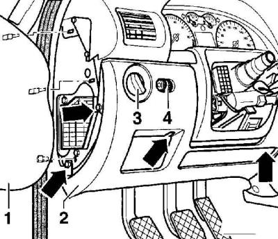
- 1 - side cover,
- 2 - bottom trim panel,
- 3 - light switch,
- 4 - headlight corrector
The arrows mark the location of the screws for fastening the bottom trim panel.
Removing the trim under the instrument cluster
- 1 - the inner side of the cladding,
- 2 - clamp,
- 3 - decorative lining
Warning: In the instrument cluster, only the indicator bulbs can be replaced. If one of the indicators fails or if there is any other defect, the instrument cluster must be replaced as an assembly.
1. Remove the steering column switches.
2. Remove the lower side trim on the driver's side, to do this, remove the plugs covering the fastening screws and unscrew the screws, see fig. Removing the lower side trim on the driver's side. Move forward and remove the lower side trim on the driver's side.
3. Remove the lower instrument panel trim on the driver's side. Remove a lateral decorative slip from the left end face of the panel of devices.
4. unscrew the screws (arrows), securing the driver's side instrument panel lower trim panel, see fig. Removing the lower trim panel of the instrument panel on the driver's side.
5. Disconnect the electrical connectors from the headlight switch and headlight range control.
6. Lift the decorative cladding from the inside (1) and using a rigid clamp (2), fix it in this position, see fig. Removing the trim under the instrument cluster.
7. Unscrew 4 screws and remove decorative facing, see fig. Removing the trim under the instrument cluster.
8. At the bottom of the instrument cluster, unscrew the two screws and remove the instrument cluster, see fig. Location of the instrument cluster mounting screws.
9. Disconnect from a back part of a combination of devices electric sockets, see fig. The location of the electrical connectors on the back of the instrument cluster.
10. Replace bulbs if necessary.
Installation
1. Installation is made in sequence, return to removal.
2. If a new instrument cluster is installed, correct the indications of the Service indicator and the kilometer counter.
Visitor comments