
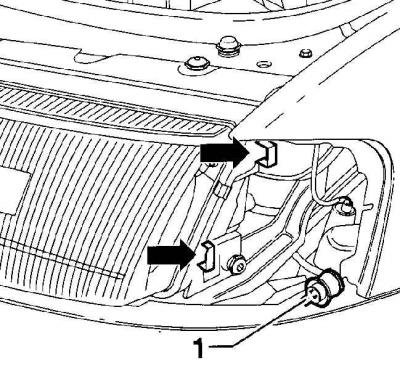
Knot for adjusting gaps around the perimeter of the headlight
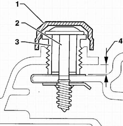
- 1 - plug,
- 2 - headlight mounting screw,
- 3 - adjusting threaded sleeve,
- 4 - with the main adjustment, the size is 3.5±2.5 mm
Farah
1. The headlight housing is not collapsible and if there are defects, the headlight housing must be replaced as an assembly.
2. Remove the front turn signal.
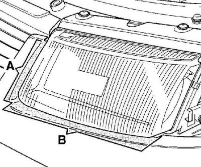
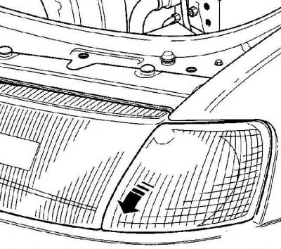
3. In order not to damage the paintwork when removing the headlight, tape the parts under the headlight with adhesive tape (IN) and from the side of the grille (A).
4. Disconnect the electrical connectors from the headlight.
5. Disconnect the electrical connector from the headlight range control motor.
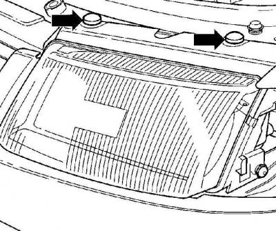
6. Using a screwdriver blade, remove the plugs covering the top headlight mounting bolts.
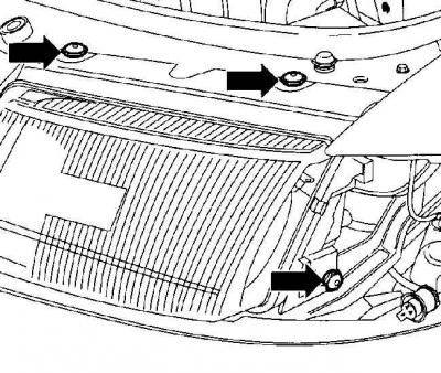
7. Remove the three headlight mounting bolts.
8. Move the headlight to the outside of the car.
9. Pull forward to remove the headlight from the vehicle. If necessary, press the headlight retainer away from the grille.
10. Being careful, install a headlight in a socket in a forward part of a body. If necessary, press the headlight retainer away from the grille.
11. Move the headlight to the center of the car.
12. Screw in and slightly, with a torque of 3.5 Nm, tighten the headlight mounting screws.
13. Check the uniformity of the gaps around the perimeter of the headlamp and, if necessary, adjust the position of the headlamp.
14. To adjust the headlight position, loosen the three headlight mounting bolts just enough to allow the headlight to move.
15. Adjust the gaps by screwing in or unscrewing the adjusting sleeve (3) wrench 17 mm, see fig. Knot for adjusting gaps around the perimeter of the headlight.
16. Tighten the headlight mounting screws to 3.5 Nm and check the gaps around the headlight.
17. Close the top headlight mounting screws with plugs.
18. Connect the electrical connectors to the headlight.
19. Install the front turn signal.
20. Check and, if necessary, adjust the headlights.
Front direction indicator
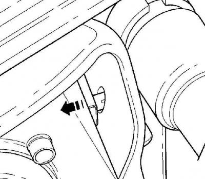
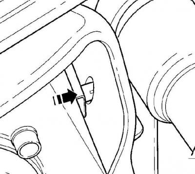
Location of guides (arrows) on the headlight for mounting the locking lugs of the front direction indicator
- 1 - electrical connector of the front direction indicator
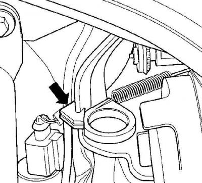
Place of fastening of the forward indicator of turns by a spring-loaded loop
Warning: Before removing the right front turn signal, remove the air intake.
1. Pull back the spring-loaded loop attached to the turn signal housing until it is disconnected, see fig. Place of fastening of the forward indicator of turns by a spring-loaded loop.
2. Pulling forward, remove the front turn signal from the vehicle.
3. Disconnect the front turn signal electrical connector.
4. If necessary, replace the front turn signal bulb.
5. Connect an electric socket of the forward index of turns, see fig. Location of guides (arrows) on the headlight to install the locking lugs of the front direction indicator.
6. Insert the front direction indicator into place and move it all the way back. Pay attention to the fact that the locking protrusions, which are mounted on the body, are included in the headlight guides and in the fender, see fig. Location of guides (arrows) on the headlight to install the locking lugs of the front direction indicator.
7. Pull back the spring-loaded loop and secure it in the middle of the holder groove.
Back light
1. Remove the rear light bulb holder.
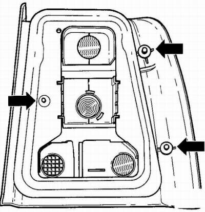
2. Unscrew the three nuts securing the rear light and, moving it back, remove it from the car.
3. Check the condition of the rear light seal and replace if damaged.
4. Insert the rear light into place and secure it with nuts, tightening them to a torque of 3 Nm.
5. Establish the holder of lamps of a back lantern.
Visitor comments