
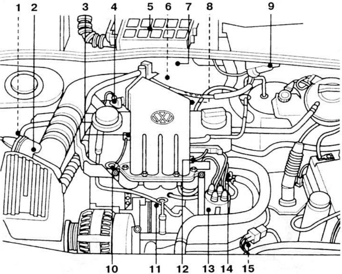
Pic. 1. Location of the components of the EDMS «Motronic 2.9» in the engine compartment: 1 - solenoid valve for adsorber purge; 2 - mass flow meter; 3 - intake air temperature sensor; 4 - throttle position sensor; 5 - controller; 6 - oxygen content sensor in exhaust gases; 7 - relay for switching on the heating of the oxygen content sensor in the exhaust gases; 8 - idle speed regulator; 9 - ignition unit (ignition coil with end stage power amplification); 10 - fuel pressure regulator; 11 - knock sensor; 12 - fuel injectors: 13 - spark moment sensor (Hall Sensor), built-in ignition distributor; 14 - coolant temperature sensor; 15 - crankshaft angular position sensor.
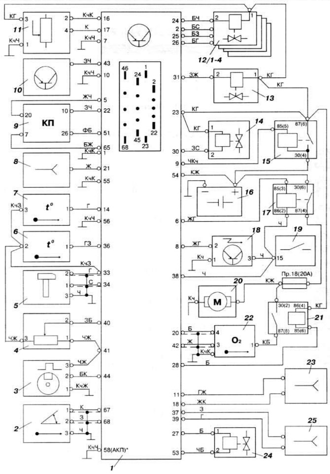
Pic. 20. Wiring diagram of the KSUD «Motronic 2.9» AEK car engine «Passat 1.6»: 1 - controller; 2 - crankshaft position sensor; 3 - ignition timing sensor; 4 - throttle position sensor; 5 - knock sensor; 6 - intake air temperature sensor; 7 - coolant temperature sensor; 8 - diagnostic connector; 9 - instrument cluster; 10 - immobilizer control unit; 11 - mass air flow meter; 12/1-4 - nozzles; 13 - solenoid valve purge adsorber; 14 - solenoid valve for exhaust gas recirculation; 15 - power relay; 16 - battery; 17 - fuel pump relay; 18 - ignition unit; 19 - ignition switch; 20 - fuel pump; 21 - relay of the oxygen content sensor in the exhaust gases; 22 - oxygen content sensor in exhaust gases; 23 - connector; 24 - idle speed regulator; 25 - connector of the automatic gearbox control unit.
NOTE: Engine «AEK» is a modification of the carburetor engine described in the main text «EZ» with KSUD «Motronic 2.9», which includes the fuel injection control subsystem is a distributed fuel injection system with a mass air flow meter and feedback on the oxygen content in the exhaust gases.
Engine idle check
Before checking engine idling, perform the following operations:
- warm up the engine (oil temperature not less than 80°С);
- check the correctness of the adjustment of the gap between the electrodes of the spark plugs and the setting of the initial ignition timing;
- make sure that the air filter element is in good condition;
- turn off all auxiliary electrical equipment and air conditioning;
- on vehicles with automatic transmission, put the selector lever in position «R» or «N».
During the test, do not allow the electric fan of the engine cooling system to turn on.
Connect the control tachometer according to the operating instructions. Start the engine at idle. Press and release the accelerator pedal sharply, then let the engine idle for 2 minutes and check the idle speed, which should be between 800-880 rpm.
The idle speed of the crankshaft is automatically adjusted by the idle speed controller according to the signals of the controller and is not subject to manual adjustment. If the idle speed is not within the specified limits, check. whether there is air leakage in the intake tract, and also check the subsystem devices, electrical wires and their connections.
Connect the gas analyzer according to the operating instructions and check the CO content in the exhaust gases, which should not exceed 0.5%.
The CO content in the exhaust gases is automatically adjusted by the controller based on the signals from the oxygen content sensor in the exhaust gases and is not subject to manual adjustment.
If the CO content does not correspond to this, check the tightness of the intake and exhaust tracts, as well as check the subsystem devices, electrical wires and their connections.
NOTE: Throttle opening is set at the factory and cannot be adjusted in service.
Fuel pressure check
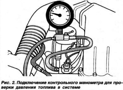
Make sure the ignition is off. Disconnect the fuel supply pipeline from the fuel rail and connect the hoses of the control pressure gauge to the pipeline opening and the rail nozzle (pic. 2). Make sure the pressure gauge valve is open. Start the engine at idle. Disconnect the vacuum hose from the fuel pressure regulator and measure the fuel pressure in the system using a pressure gauge, which should be about 3.0 kgf / cm2. Connect the vacuum hose to the fuel pressure regulator and measure the fuel pressure in the system using a pressure gauge, which should be about 2.5 kgf / cm2. Stop the engine and after 10 minutes determine the residual fuel pressure in the system using the pressure gauge, which must be at least 2.0 kgf/cm2.
Checking the performance of the fuel pump supply voltage
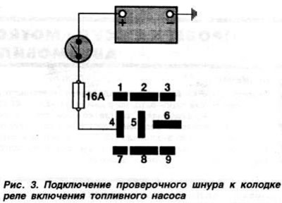
Performance check. Make sure the ignition is off. Disconnect the fuel supply line from the fuel rail. Connect one hose of the control pressure gauge to the pipeline opening, and lower the other hose of the pressure gauge into a measuring vessel. Open the manometer cock. Remove the fuel pump enable relay. Connect with a test cord to a switch and a built-in 16 A fuse «4» (pic. 3) relay sockets with terminal «+» battery. Operate the fuel pump with the switch. as soon as the fuel pressure on the pressure gauge reaches 3 kgf / cm2, close the pressure gauge valve. Turn off the fuel pump with the switch, pour the fuel out of the measuring vessel, then immerse the pressure gauge hose into it again, operate the fuel pump with the switch for 30 s and determine the amount of fuel leaked into the vessel, which should be 0.49-0.67 l. Disconnect the control pressure gauge and connect the fuel supply line to the fuel rail.
Checking the supply voltage. Turn on the ignition, while the fuel pump should turn on for about 1 s. If this does not happen, turn off the ignition, remove the fuel pump enable relay, connect the test cord as described above. The fuel pump should run continuously while the test cord switch is on. If the pump does not work, check fuse #18. If he is whole. Disconnect the wiring harness from the fuel pump. Turn on the test cord switch and measure the presence of battery voltage at the terminals «1» and «4» pads (end terminals of the block). If there is no voltage, check the wires and their connections in the fuel pump circuit.
Checking fuel injectors
Make sure the ignition is off. Disconnect the wire blocks from the injectors one by one and check the resistance of their windings, which should be in the range of 14.0-21.5 Ohms, then turn the engine crankshaft with a starter and. by connecting a voltmeter to one of the injector terminals and «weight», check the supply voltage of the injector, which must be equal to the battery voltage. If there is no voltage, check the wires and their connections, as well as the KSUD relay. Connect the LED tester to the terminals of the injector wire block, turn the engine crankshaft with the starter, while the tester LED flashes. If this does not happen, check the wires and their connections in the circuit of this injector.
Throttle position sensor test
Make sure the ignition is off. Disconnect the throttle position sensor connector, connect an ohmmeter to the terminals «1» and «2» sensor pads (pic. 4) and check the readings of the ohmmeter, which should be in the range of 2.5-4.0 kOhm. Slowly open throttle. In this case, the resistance on the ohmmeter should gradually decrease.
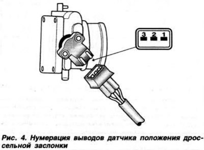
Connect an ohmmeter to the leads «2» and «3» sensor pads and check its readings, which should be in the range of 1.0-2.0 kOhm. Slowly open throttle. In this case, the resistance on the ohmmeter should gradually increase. Connect an ohmmeter to the leads «1» and «3» sensor pads and check its readings, which should be in the range of 1.6-2.4 kOhm.
Turn on the ignition. Connect a voltmeter to the terminals «1» and «3» sensor wiring blocks and check the sensor supply voltage, which should be about 5 V. If it does not match this, check the wires and their connections in the sensor circuit.
Checking the Mass Air Flow Meter
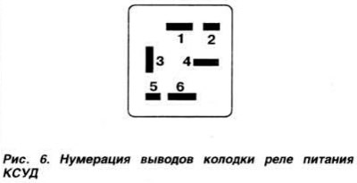
Make sure the ignition is off. Disconnect the meter connector. Connect an ohmmeter to the terminal «1» (pic. 5) meter and «weight», measure the resistance, which should be equal to zero. connect leads «4» and «6» (pic. 6) relay pads with a jumper with a switch. Turn on the switch and, by connecting a voltmeter to the terminals «3» and «1» meter, measure the voltage of its supply, which should be equal to the voltage of the battery. If abnormal, check the wires and their connections in the meter circuit.

Connect the meter connector. Slide the protective cover of the connector and connect the voltmeter to the terminals «4» and «2». Start the engine at idle. Measure the voltage at the terminals of the meter. Press the accelerator pedal sharply two or three times, while the voltmeter needle should fluctuate.
Checking the intake air temperature sensor
Make sure the ignition is off. Disconnect the wiring harness from the sensor. Connect an ohmmeter to the sensor terminals and measure the resistance, which at an ambient temperature of 0°C should be in the range of 5.0-6.5 kOhm, at 10°C - 3.35-4.4 kOhm, at 20°C - 2, 25-3.0 kOhm, at 30°C - 1.5-2.1 kOhm, at 40°C - 950-1400 Ohm, at 50°C - 700-950 Ohm, at 60°C - 540-675 Ohm, at 70°C - 400-500 Ohm and at 80°C - 275-375 Ohm
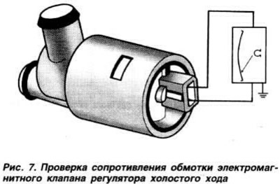
Checking the idle speed controller
Make sure the ignition is off. Disconnect the regulator connector. connect an ohmmeter (pic. 7) to the terminals of the regulator and measure the resistance of the winding of its solenoid valve. which should be within 7-10 ohms, and on a warm engine (oil temperature not less than 80°С) may be closer to the upper limit
Checking the coolant temperature sensor
Make sure the ignition is off. Disconnect the coolant temperature sensor connector. Remove the sensor from the engine and immerse it in an electrically heated container filled with coolant. Connect an ohmmeter to the leads «1» and «3» (pic. 8) sensor and check the resistance of the sensor, which at a coolant temperature of 0°C should be in the range of 5.0-6.5 kOhm, at 10°C - 3.35-4.4 kOhm, at 20°C - 2.25- 3.0 kOhm, at 30°C - 1.5-2.1 kOhm, at 40°C - 950-1400 Ohm, at 50°C -700-950 Ohm, at 60°C - 540-675 Ohm, at 70°C - 400-500 Ohm, at 80°C - 275-375 Ohm, at 90°C - 200-290 Ohm and at 100°C -150-225 Ohm.
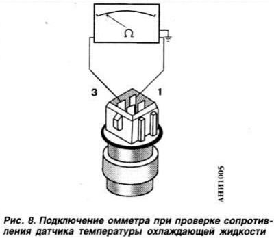
The coolant temperature sensor can be checked without removing it from the engine.
Checking the crankshaft angle sensor
Make sure the ignition is off. Disconnect the block of wires from the sensor and measure the resistance of the sensor, which, when measured between the terminals «1» and «2» (pic. 9) should be 500-700 ohm, between pins «1» and «3», «2» and «3» - endless.

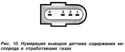
Exhaust oxygen sensor test
Make sure the ignition is off. Disconnect the wiring harness from the sensor. Turn on the ignition and measure between the terminals «3» and ««4» (pic. 10) supply voltage sensor, which should be about 0.5 V.
Start warm engine (oil temperature not less than 80°С) at idle, depress the accelerator pedal sharply and let the engine idle for 2 minutes. Disconnect the wiring harness from the sensor. connecting a voltmeter to the output «4» sensor and «mass», measure the voltage whose value is to be changed.
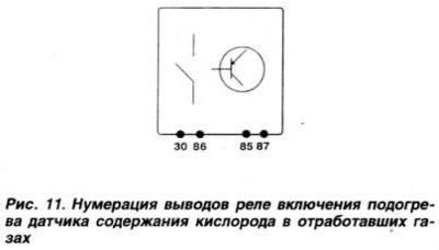
Checking the relay for switching on the heating of the oxygen content sensor in the exhaust gases
Resistance check. Make sure the ignition is off. Remove the relay and measure the resistance between the terminals «30» and «87» (pic. eleven) relay (R=∞). To plug «+» battery to the output «85» turnip. «-» - to the conclusion «86». Never change the polarity of the battery connection to prevent damage to the relay. Measure resistance between terminals «30» and «87» relay (R=0).
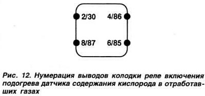
Checking the supply voltage. Make sure the ignition is off. Remove the power supply relay for the KSUD, the relay for turning on the fuel pump and the relay for turning on the heating of the oxygen content sensor in the exhaust gases. Connect the test cords to the output switches «4» (pic. 3) blocks of the relay of inclusion of the fuel pump and «+» battery, as well as conclusions «4» and «6» (pic. 6) power relay pads KSUD. Turn on the cord switches and, by connecting a voltmeter in series to the terminals «2/30» and «6/85» (pic. 12) relay pads for switching on the heating of the oxygen content sensor in the exhaust gases, measure the voltage, which should be equal to the battery voltage.
Checking the heating element of the oxygen content sensor in the exhaust gases
Make sure the ignition is off. Disconnect the wiring harness from the exhaust oxygen sensor. Start the engine at idle and connecting a voltmeter to the terminals «1» and «2» pads of wires, measure the voltage, which should be equal to the battery voltage.
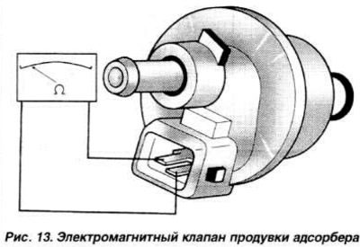
Canister purge valve check
Make sure the ignition is off. Disconnect from valve (pic. 13) wiring harness and by connecting an ohmmeter between the valve terminals, measure the resistance of the valve winding (R=40-80 Ohm) Start the engine at idle and connecting a voltmeter to the output «1» wiring harnesses and «weight», measure the voltage. which should be equal to the battery voltage. If the voltage does not match this, check the wires and their connections in the valve circuit.
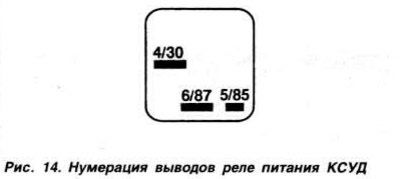
Checking the power relay KSUD
Resistance check. Make sure the ignition is off. Remove the relay and measure the resistance between the terminals «30» and «87» (pic. 14) relay (R=∞) To plug «+» battery to the output «30» relay, «-» - to the conclusion «85». Never change the polarity of the battery connection to prevent damage to the relay. Measure resistance between terminals «30» and «87» relay (R=0).
Checking the supply voltage. Turn on the ignition, while a click should be heard from the operation of the power supply relay of the KSUD. If it is not heard, check the fuse of the KSUD Turn off the ignition, remove the relay and. connecting a voltmeter to the output «4» (pic. 6) relay pads and «weight», measure the voltage. which should be equal to the battery voltage. If the voltage does not match this, check the wires and their connections in the relay circuit.
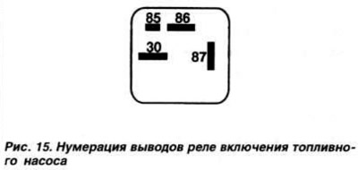
Check of the relay of inclusion of the fuel pump
Resistance check. Make sure the ignition is off. Remove the relay and measure the resistance between the terminals «30» and «87» (pic. 15) relay (R=∞). To plug «+» battery to the output «86» relay, «-» - to the conclusion «85». Never change the polarity of the battery connection to prevent damage to the relay. Measure resistance between terminals «30» and «87» relay (R=0).
Checking the supply voltage. Turn on the ignition, and a click should be heard from the operation of the turnip. If this does not happen, check the integrity of fuse No. 18. Turn off the ignition, remove the relay and, by connecting a voltmeter in series to the terminals «2» and «6» (pic. 3) relay pads and «mass» and turning the ignition on and off, measure the voltage, which should be equal to the battery voltage. If the voltage does not match this, check the wires and their connections in the relay circuit.
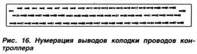
Controller check
Checking the supply voltage. Make sure that the power supply relay is OK (see above). Check if the ignition is off Disconnect the controller connector. Connect a voltmeter in series to the terminals «54», «23» (pic. 16) (connect with this check the output «9» wire blocks with «weight») wiring harnesses and «mass» and measure the voltage, which should be equal to the battery voltage.
Turn on the ignition, connect a voltmeter to the output «38» wiring harnesses and «mass» and measure the voltage, which should be equal to the battery voltage. If the voltage does not correspond to this, check the wires and their connections, as well as the KSUD relay.
Checking connection with «weight». Make sure the ignition is off. Disconnect the controller connector. Connect an ohmmeter in series to the terminals «1», «7», «10», «55», «56», «58» (on vehicles with automatic transmission) And «mass» and measure the resistance, which in all cases should be R=0. Otherwise, check the wires and their connections in the KSUD circuit.
Checking the speed sensor
Make sure the ignition is off. Disconnect the controller connector. On vehicles with automatic transmission, place the selector lever in position «0». Raise the front of the car and place on stands. Turn on the ignition and, rotating the left front wheel, measure the voltage between the terminals «56» and «65» controller wire pads, which should fluctuate between 0-4 V (at least).
UOZ control subsystem
NOTE:
1. Before cranking the engine crankshaft with a starter, remove the power supply relay for the KSUD. not to damage the exhaust gas converter.
2. UOZ is automatically optimized by controller commands depending on the engine operation mode and is not subject to adjustment in operation.
Check for spark
Make sure the ignition is off. Remove fuse #18. Relieve residual fuel pressure in the system. Disconnect the high voltage wire from any spark plug and insert a test plug into the end of the wire. Using pliers with insulating handles, bring the candle 6 mm to «mass». Turn the crankshaft of the engine with a starter, while a powerful spark of a bluish color should be observed. Repeat the test for the remaining spark plugs. If there is no spark, check the high voltage circuit of the PTO control subsystem.
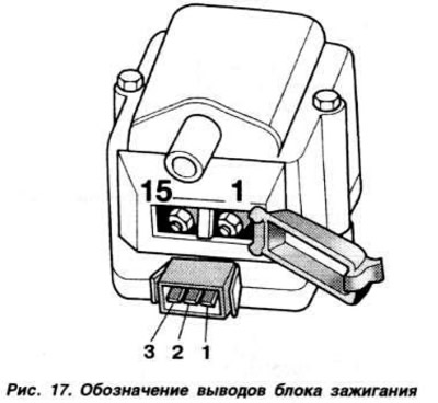
Checking the ignition unit
Checking the ignition coil. Make sure the ignition is off Disconnect the ignition module connector. Disconnect the high voltage wire from the ignition unit. Remove the ignition coil low voltage circuit terminal cover. connecting an ohmmeter to the terminals «15» and «1» (pic. 17). measure the resistance of the primary winding of the ignition coil (R=0.5-1.2 ohm). Connect an ohmmeter to the terminal «15» low voltage and high voltage output and measure the resistance of the secondary winding (R=3.0-4.0 kOhm).
Checking the final stage of power amplification. Make sure. that the ignition is off. Disconnect the ignition module connector. Connect an ohmmeter to the terminal «1» block of wires of the block of ignition and «weight» and measure the resistance (R=0). If the resistance does not match this, check the wires and their connections. Turn on the ignition. By connecting a voltmeter to the extreme terminals of the ignition block wire block, check the supply voltage, which should be equal to the battery voltage. If the voltage does not match. check the wires and their connections. Switch off the ignition. Remove fuse #18. Relieve residual fuel pressure in the system. Connect the LED probe to the terminals «2» and «3» ignition block wires. Turn the engine crankshaft with a starter, while the probe LED should flash. If this does not happen, check the wires and their connections in the ignition unit circuit. Connect the ignition module connector. Remove the ignition coil low voltage terminal cover and connect an LED probe to them. Turn the engine crankshaft with the starter. while the probe LED should flash. If this does not happen, the final stage of power amplification has failed and the ignition unit must be replaced.
Checking the Spark Torque Sensor
Make sure the ignition is off. Disconnect the wiring harness from the ignition distributor. Connect an ohmmeter to the terminal «1» (pic. 18) wiring harnesses and «weight» and measure the resistance (R=0). Connect a voltmeter to the terminals «1» and «3» wire blocks. Turn on the ignition. Measure the voltage, which must be at least 4.5 V. Connect the connector of the ignition distributor. Remove fuse #18. Relieve residual fuel pressure in the system. Move the protective cover of the ignition distributor connector, connect the LED probe to the extreme terminals of the connector. Turn the engine crankshaft with a starter, while the probe LED should flash.

Checking the knock sensor
Make sure the ignition is off. Disconnect the wiring harness from the sensor and unscrew the sensor from the cylinder block. Check the mating surfaces of the cylinder block and sensor for signs of corrosion and contamination. Screw the sensor into the cylinder block (tightening torque 2.0 kgf·m). Connect an ohmmeter to the leftmost terminal of the sensor wiring block and measure the resistance (R=0). Measure the resistance between the sensor leads (R=∞).
Fault codes KSUD «Motronic 2.9» engine «AEK»
| Print Code | Fault location or violated parameter |
| 00281 | Vehicle speed sensor |
| 00513 | crankshaft angle sensor |
| 00515 | spark torque sensor |
| 00518 | Throttle position sensor |
| 00522 | coolant temperature sensor |
| 00524 | Knock sensor |
| 00525 | Exhaust oxygen sensor |
| 00527 | intake air sensor |
| 00532 | Controller supply voltage |
| 00533 | idle speed controller |
| 00535 | Knock sensor control circuit |
| 00537 | Exhaust Oxygen Sensor Control Circuit |
| 00543 | Exceeding the maximum allowable engine speed |
| 00549 | Short circuit in a chain of a combination of devices |
| 00553 | Mass air flow meter |
| 00561 | Incorrect signal from the oxygen content sensor in the exhaust gases |
| 00609 | Ignition Unit Low Voltage Circuit |
| 00640 | Relay for switching on the heating of the oxygen content sensor in the exhaust gases |
| 01242 | Controller control schemes |
| 01247 | Canister purge valve |
| 01249 | Nozzle of the 1st cylinder |
| 01250 | Nozzle 2nd cylinder |
| 01251 | Nozzle of the 3rd cylinder |
| 01252 | Nozzle 4th cylinder |
| 01259 | Fuel pump relay |
| 17978 | Immobilizer ECU |
| 65535 | Faulty controller |
* Polling the ROM of the controller is performed in the same way as on the ABS engine with KSUD «Mono-MotroniC», see main text.
NOTE: When troubleshooting, refer to the table in Appendix II.
Visitor comments