
Repair kit for plugs 1Н0 698 311А
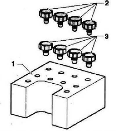
- 1 - Transport protection (Styrofoam)
- 2- Plugs M10
- 3 - Plugs M12
Place of installation. The control unit is screwed to the hydraulic unit and is located on the left side of the engine compartment under the battery bracket.
WARNING: It is forbidden to change the shape of the brake lines near the hydraulic unit!
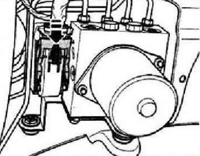
Read and write the existing control unit coding. On a car equipped with a radio with a code, find it out by making a request if necessary. Disconnect the negative battery terminal. Remove the air intake hose, air filter and battery. Remove battery bracket. Open the wiring box, remove both wiring harnesses and set them aside. Remove wiring box from console. Push the red lock -in the direction of the arrow- down.
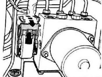
Unlock and disconnect connector from control unit -arrow-.
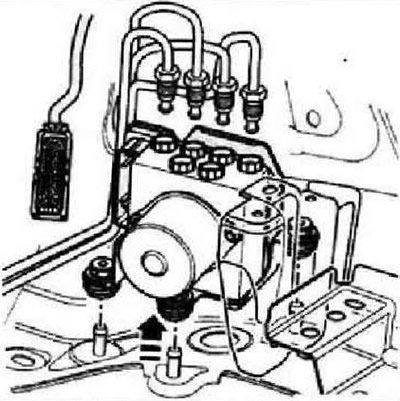
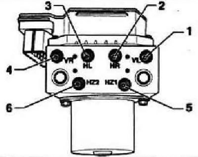
Install spacer -VAG 1869/2-. Connect the hose of the bleeder container to the bleeder fittings of the front left and rear right calipers and loosen the bleeder fittings. Depress brake pedal at least 60 mm using spacer -VAG 1869/2-. Tighten the bleeder fittings of the front left and rear right calipers. Do not remove spacer -VAG 1869/2-. Place a sufficient amount of non-fibrous cloth under the control unit and hydraulic unit. Avoid contact with brake fluid. Mark and disconnect both brake lines from the GTZ. Seal the lines and tapped holes immediately with plugs from the 1H0 698 311 A set. Mark the position of the rest of the brake lines (to brake calipers), then unscrew them and install the plugs. Remove hydraulic unit with control unit upwards from damping supports -arrow-.
Installation
Instruction: It is not allowed to remove all plugs from the new hydraulic unit at once. Each plug is removed just before the corresponding brake line is connected. If all the plugs are removed at once, a brake fluid leak may occur, and it will no longer be possible to guarantee sufficient filling and bleeding of the hydraulic unit. When installing the hydraulic unit, the damping feet must not be pressed out of the bracket. The damping supports must lie against the side member.
Installation is carried out in the reverse order. Sequence of an inhaling of unions of brake pipelines. Remove spacer bar -VAG 1869/2-. Bleed the brake system. Encode the radio. Code control unit -J104- using the tester - Vehicle diagnosis, testing and information system VAS 5051 in Guided Fault Finding. In this case, the basic setting of the steering angle sender -G85-, the lateral acceleration sender -G200-, the longitudinal acceleration sender -G251- and the brake pressure sender -G251- must be carried out.
Tightening torques
| Hex head bolt for attaching the hydroblock to the bracket | 8 Nm |
| Fastening of brake pipelines to the block A8S. Thread M10x1, M12x1 | 14 Nm |
Visitor comments