



Wheel alignment
1. The camber angle is adjusted by releasing the upper control arm support nut and using an Allen key on the head of the support bolt to turn the support bolt. This will cause the eccentric washers to rotate and move the suspension arm relative to the side of the body.
Steering axis tilt angle
2. The steering axis angle varies according to the installation of the radial arms. Provided that the length indicated in Figure 11.12 is between 529 and 540 mm, the steering axis angle will be within the acceptable limits. When installing the lever after disassembly or replacement, set its length within the range of 532 to 537 mm.
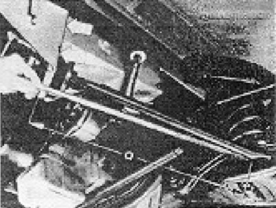
Figure 11.12. Radial arm installation diagram (Section 6). Measure the distance "a" from the inner edge of the bracket cutout to the edge of the curved part of the bracket (indicated by the arrow).
Wheel alignment
3. Set the front wheels to the straight-ahead position. The vehicle should be positioned on a level, flat surface and supported by its normal load.
4. Purchase an auxiliary tool. It can be obtained from a specialist workshop, or made from a steel tube, bent appropriately to go around the crankcase and housing, and having a mounting screw and locking nut at one end.
5. Using this tool, measure the distance between the inner arches of the wheels (at the height of the hub) to the rear of the wheel. Move the car forward to turn the wheels 180 degrees (half a turn), and measure the distance between the inner rims of the wheels, again at the height of the hub, at the front of the wheel. The last measurement must be less than the first by the corresponding amount (see Specifications).
6. If the toe-in is incorrect, loosen the lock nuts on the adjustable tie rod end and rotate the tie rod. The opposite end is not adjustable. Rotate the tip a quarter turn, then take measurements again.
7. When finished, tighten the lock nuts without disturbing the installation of the tips. Check that the ball joints are centered.
8. While keeping the front wheels still in the straight ahead position, check the alignment of the center marks as described in Section 25. If they don't align, disconnect the link rod from the steering gear lever, loosen the locking nut, and adjust the ball joint until the center marks line up and the ball joint's cone pin fits directly into the eye of the lever.
9. If the position of the steering wheel spokes remains incorrect, remove the steering wheel as described in Section 25 and change its position on the splines.
Visitor comments