



31. The hydraulic fluid reservoir is installed behind the left headlight trim panel.
32. The power steering components are shown in Figure 13.90. Individual power steering components cannot be repaired and must be replaced with new ones if they fail.
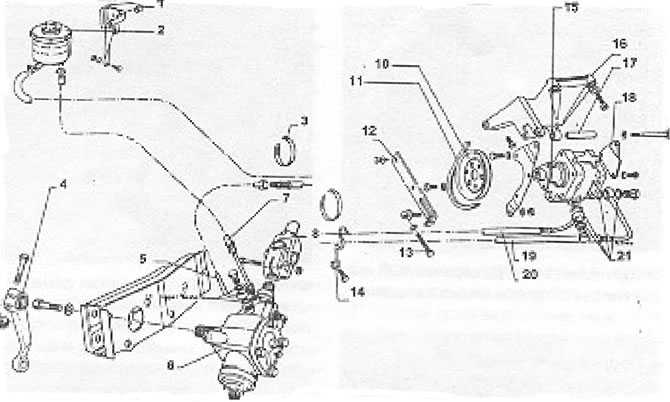
Figure 13.90. Power steering (section 14): 1 - Tank bracket; 2 - Tank; 3 - Clamp; 4 - Steering arm; 5 - Feed tube; 6 - Power steering; 7 - Return hose; 8 - Cardan joint; 9 - Copper washers; 10 - V-belt pulley; 11 - Belt; 12 - Spacer; 13 - Tension screw; 14 - Hose holder; 15 - Pump; 16 - Console; 17 - In the bushing; 18 - Pump bracket; 19 - Expansion hose; 20 - Suction hose; 21 - Medina pucks.
33. To work with power steering, the following changes were made to the design of the manual steering control.
34. The holes in the chassis for the steering gear mounting bolts have been enlarged.
35. The connecting disk between the steering box and the steering column has been replaced with a cardan joint.
36. The steering column has been shortened.
37. If the power steering fails, the manual steering continues to function, but the force required to apply to the steering wheel increases significantly. The power steering should be repaired at the first opportunity.
Visitor comments