



2. Set the steering gear to the center position as described in previous Section.
3. Remove the cover from the steering column by pulling it sharply to overcome the resistance of its mounting clamp (see photo 26.3).
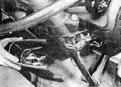
Photo 26.3. Removing the central section of the steering column cover.
4. Disconnect the wiring from the steering column switches from the plugs.
5 At the base of the column, unscrew and remove the through bolt of the cotter pin joint.
6. At the top of the column, detach the support bracket.
(The original article is posted on the website: www.VWmanual.ru)
7. Remove the column and shaft assembly together with the steering wheel from the vehicle cabin.
8. The column switches and the steering lock can be removed as described in Chapter 10.
9. The flexible joint and cotter pin joint components can be disassembled (mark the position of the ground wire), however, further disassembly is not recommended. It is better to purchase a new column/shaft design.
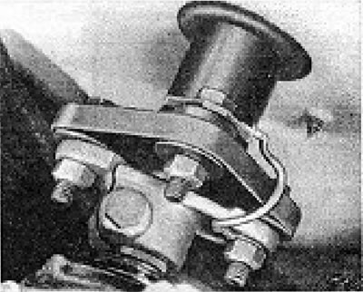
Figure 11.37. Steering column flexible joint ground wire.
10. Installation is carried out by performing the above steps in reverse order.
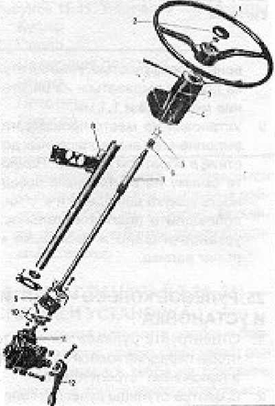
Figure 11.38. Steering column (LT 28, 31, 35): 1 - Steering wheel; 2 - Sound signal button; 3 - Upper casing; 4 - Lower casing; 5 - Spring; 6 - Support ring; 7 - Steering shaft; 8 - Column tube; 9 - Floppy disk; 10 - Cotter pinned joint; 11 - Steering box; 12 - Lever.
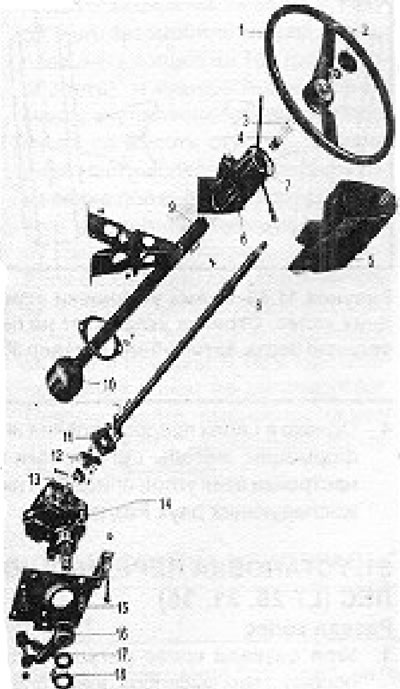
Figure 11.39. Steering column (LT 40, 45): 1 - Steering wheel; 2 - Sound signal buttons; 3 - Spring; 4 - Support ring; 5 - Lower casing; 6 - Intermediate casing; 7 - Upper casing; 8 - Steering shaft; 9 - Column tube; 10 - Backstage; 11 - Floppy disk; 12 - Cotter pinned joint; 13 - Clamp; 14 - Steering box; 15 - Support plate; 16 - Lever; 17 - Nut; 18 - Locking plate.
Visitor comments