



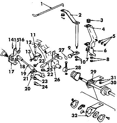
Figure 355. Gear selection mechanism: 1 - traction; 2 - gear selection rod; 3 - bushing; 4 - gear shift rod bracket; 5 - nut and washers; 6 - plate; 7 - bushing; 8, 10, 24, 31 - nuts and washers; 9 - gear selection rod; 11 - axis; 12 - Angle lever bracket; 13 - bolt; 14 - hairpin; 15 - hinge; 16, 18, 21, 22 - rubber bushings; 17 - bracket; 19 - front rod; 20, 26 - wings; 23 - sliding sleeve; 25 - rear gear shift rod; 27 - gasket; 28 - clamp; 29 - Gear shift lever bracket; 30 - gear selection rod; 32 - bracket plate
The rod 1, which connects the gear selection rod 2 to the bracket 17, has differently curved ends. The end of the rod that has the designation must be connected to the bracket 17. The front and rear gear selection rods can only be removed when the locks from the plastic tips have been removed with a screwdriver.
The gear shift lever can only be installed on the rod in one position.
When installing the levers, coat all hinges and sliding surfaces with molybdenum disulfide grease.
The adjustment of the selection mechanism is performed as follows:
- Set the gear selector lever to neutral position.
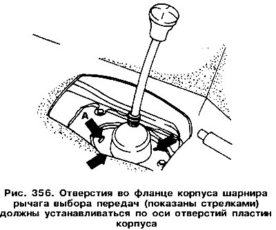
- Check that the holes in the gear selector lever joint housing flange are aligned (arrows in figure 356) with the hinge housing holes. The threaded holes should be in the middle of the elongated holes. If not, then you need to unscrew the bolts and move the hinge flange.
- Loosen the gear selector shaft coupling nut (figure 357). The rod should now move easily.
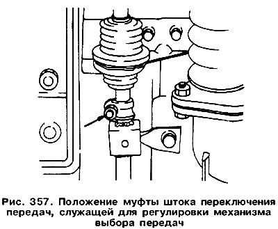
Pull off the long rubber boot and slide it along the rod. Sometimes additional loosening of the bolts securing the hinge housing plate is necessary.
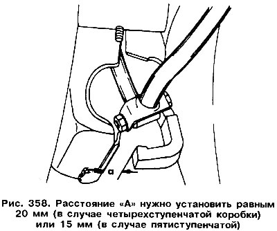
Prepare a 20 mm wide strip of sheet metal (dimension "A" in Figure 358) and place it in the position shown in the figure. In this position, tighten the rod coupling nut.
(View the original on this resource: «www.vwmanual.ru»)
Check if all gears engage easily.
Visitor comments