



If you need to replace the toothed ring gear of the main transmission, you need to drill out the rivets with a 12 mm drill. This is not difficult, since the rivet heads have a recess in the middle (see figure 333). After removing the heads, the rivets should be knocked out.
Heat the ring gear to 100°C and place it on the differential housing. Use two bolts screwed into the housing from opposite sides as a guide. New special bolts, washers and nuts should be used for installation (this kit is designated in the catalog by number 171498088). Nuts and bolts are tightened to a torque of 70 Nm.
If only the differential gears were replaced without removing the ring gear, the cut rivets should be replaced with two bolts.
Insert the satellite gears together with the washers. Carefully install the satellite axle.
Insert the axle gears through the holes so that they engage with the satellites.
Install the axle drive shafts and select the thickness of the retaining rings as described below:
- Move the axle drive shaft flange up to the satellite axis and move the axle gear towards the housing wall.
- Insert the retaining ring and check that it does not get pinched; if it is pinched, replace it with a thinner one.
- Select the locking ring for the second axle gear of the wheel in the same way. The installation of the main gear is carried out in the reverse order of disassembly. The main gear must be installed before installing the axle drive shafts.
Gearbox housing assembly. Assembly is performed in the reverse order of dismantling. Observe the following recommendations:
- Make sure that the differential housing bearings are fully seated in the gearbox housing. Tighten the nuts of the three bolts to 15 Nm.
- Check if the reverse gear shaft is in the correct position.
- The upper part of the gearbox housing will be laid down,; on the bottom and with a rod of a suitable diameter (or a special one - 30-23) press the ball bearing, as well as the housing onto the shaft. Do not forget to install the adjusting washer.
- Tighten the bolts that connect the two parts of the crankcase to a torque of 25 Nm. The two short bolts are designed to install the gearshift rod.
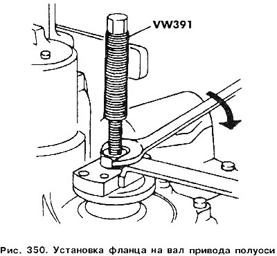
When installing drive shaft flanges, use a fixture (figure 350). Place a lock washer on the shaft and install it in the groove using a pipe of a suitable I diameter. Install the parts shown in figure 341.
(The information is presented on the website: VWmanual)
When installing the clutch fork, make sure that the bent ends of the return spring do not rest against the crankcase wall, but that its central part grips the fork. Install both retaining rings.
Visitor comments