
Mark the position of the casing in relation to the flywheel (for example, marking both parts with a core).
Open gradually and «criss-cross» six bolts securing the flywheel, releasing it from spring pressure.
Remove the flywheel and driven disc.
Using a screwdriver, remove the circlip 8 (see fig. 209) from the groove of the connecting disc 7.
Remember how the ring was installed so that it will take the same position when reassembling.
Remove the driven disk.
Remove the bolts securing the clutch pressure plate to the crankshaft flange and remove the clutch.
Wipe the inside of the flywheel and pressure plate.
Each time the engine or gearbox is removed, the clutch must also be removed to check its technical condition.
A procedure for testing individual clutch parts has been given for the clutch of gasoline engines.
Clutch installation takes place in reverse order.
In doing so, follow the instructions below.
Clutch pressure plate 5 (see fig. 209) put on the crankshaft neck and place the central ring under the bolts. Coat the bolts with thread locking compound «D6» and screw. Tighten gradually «criss-cross» torque of 75 Nm.
If motor plate 4 has been removed, place it on the pin during assembly. Replace gasket 1.
Lubricate the hole under the lever.
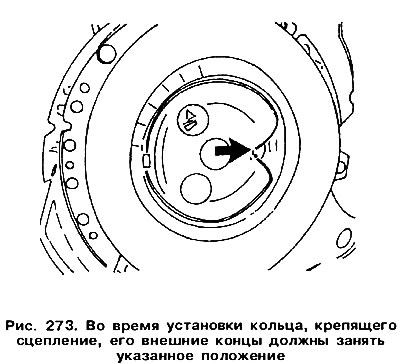
Install disc 7 and circlip 8 in the grooves so that both ends are in the position shown in fig. 273.
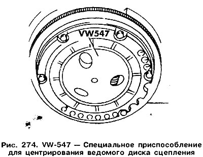
Insert Drive Disk (hub out), while maintaining its central position. For this, a special device VW-547 is used (pic. 274).
Install the flywheel and attach it with bolts, tightening them with a torque of 20 Nm.
Visitor comments