
Remove the gearbox (see here).
Mark with a punch the relative position of the flywheel and pressure plate.
Remove the six pressure plate mounting bolts. At this time, the flywheel must be locked.
Remove pressure plate. If it cannot be removed from the flywheel pins, you can use a screwdriver. Remove the driven disk. Please note that the protruding part of its hub is directed towards the gearbox, so that later there are no difficulties with installation.
Wipe the inside of the flywheel and check the condition of its running surface. If there are deep grooves from protruding rivets from the driven disk, the flywheel should be removed. Each time the engine or gearbox is removed, the clutch must be removed to check its technical condition.
Check that the pressure plate and its casing are not damaged or warped. If they are damaged, the pressure plate assembly must be replaced.
Check for damage to the damper springs of the driven disc and whether the protruding part of the disc hub is not badly worn. A driven disc with oily friction linings must be replaced, as the linings cannot be cleaned.
Check the suitability of the overlays by measuring the depth of the rivet heads in the overlay with a depth gauge. If this dimension is less than 0.30 mm or approaches this value, the disc should be replaced.
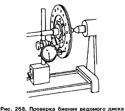
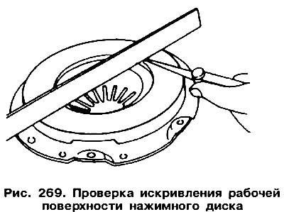
To check the axial runout of the driven disk, it is necessary to put it on the input shaft of the gearbox or on a round rod well suited to the diameter of the hole in its hub, which is installed in the centers of the lathe. Move the indicator to the outer edge of the disc (pic. 268) and, slowly rotating the dial, read the indicator. If the runout exceeds 0.4, the disk must be replaced or try to straighten it. Check the play of the driven disc hub on the splined surface of the gearbox shaft. Place the disk on the shaft and, grabbing the outer edge with two fingers, shake the disk in both directions; a play exceeding 0.4 mm indicates wear on the spokes, most often the disc hub. Check the degree of wear of the ends of the petals of the pressure plate spring. If deep scratches are found on them, the pressure plate assembly must be replaced. The ends of the spring petals must lie in the same plane with a deviation of±0.25 mm. Curved ends need to be straightened, usually a special device is used for this. Place a metal ruler on the working surface of the pressure plate and measure the gap (warpage), as shown in fig. 269. The maximum allowable gap is 0.3 mm, with a larger gap, the pressure plate should be replaced as an assembly.
 |  |
The clutch is installed in the reverse order. In doing so, you need to pay attention to the following:
- Cover the threaded part of the flywheel mounting bolts with a fixing compound before installation «D6» for threaded connections. Flywheel bolt torque 100 Nm.
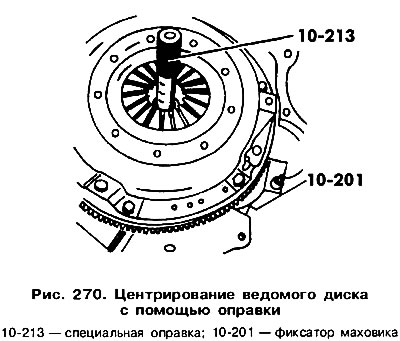
- When installing the old clutch assemblies, you need to remember the marks made before disassembly. The new pressure plate is installed relative to the flywheel in an arbitrary way. The clutch must be correctly installed on the flywheel pins. To center the driven disk, use the special mandrel Nq 10-213 (pic. 270). A used gearbox input shaft can also be used for this purpose. Tighten the casing mounting bolts evenly with a torque of 25 Nm. The flywheel must be locked.
Reinstall the engine or gearbox, adjust the free play of the clutch pedal.
Visitor comments